Transcription of Four-position sectionalizing loadbreak switches catalog
1 Eaton's Cooper Power series Four-position sectionalizing loadbreak switch is designed for use in transformer (mineral) oil, Envirotemp FR fluid, or an approved equivalent fluid-filled pad-mounted transformers or distribution switchgear. The switches meet the full requirements of the latest revision of both IEEE and IEC switches can be used on single- and three-phase grounded wye or delta systems. They are used in underground residential applications with loop feed, and in three-phase commercial industrial installations where the ability to use an alternative source of power is necessary. They can also be used to switch on and off a primary cable tap on a under-oil switch can be installed near the transformer core/coil assembly, thus minimizing cable capacitance.
2 With cable capacitance minimized and all three phases switched simultaneously, the like li hood of ferroresonance is greatly reduced. All switches are hotstick operable and available in several different blade configurations (Refer to Table 4).Eaton's Cooper Power series sectionalizing switches rotate 360 in either direction for alternate source selection. An externally installed limiting plate prevents ro ta tion to positions other than the one desired. A spring-loaded activating mechanism ensures quick loadbreak action and positive contact engagement through all positions. The Make-Before-Break (MBB) switches provide uninterrupted power during sectionalizing loadbreak switchesGeneralOEM EquipmentCatalog Data CA800005 ENEffective June 2015 Supersedes 800-64 August 2012 COOPER POWERSERIESMake-before-break features Improves system reliability by eliminating momentary interrup-tions during switching operations typically associated with Break-Before-Make (BBM) sectionalizing switches .
3 Replaces 2 or 3 two position loadbreak switches depending on application (Choose V-blade or T-blade type). Simplifies operational procedures. Make-Before-Break design is only available for V- and T-blade switch Available for both 12 kA and 16 kA applications. ratings from 200 A to 630 A and from 15 kV to 38 kV. Tested in mineral oil and Envirotemp FR3 fluid. All electrical switching tests performed at third-party certified test laboratories 5000 mechanical operations (meets IEC class M2 switch). All silver plated copper current path. Similar footprint as previous 10 kA switches (See Tables 3 and 4). The Ring-Mount System option offers easy and fast installation. Special vertical mounted switches available for cover mounted testsTests are conducted in accordance with Eaton requirements: Physical Inspection Mechanical operations Operating torque Contact pressure Switch contact resistanceInstallationThe switch is either horizontally or vertically mounted, depending on the application and the selected switch type.
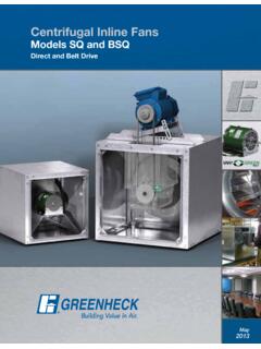
4 The vertically mounted switch is typically used in transformers/switchgear installed below grade, where the switch would be mounted in the cover of that par-ticular equipment. All exposed parts of the vertically mounted switch are made from stainless steel or other non-corrosive materials. Both types of switches , including the mechanism, must be completely immersed under the insulating :NFor all mounting systems, refer to Service Information MN800002EN sectionalizing Switch Installation Instructions for more detailed installation Data CA800005 ENEffective June 2015 Four-position sectionalizing loadbreak 2. Makt-BtfNr t-Brtak swioch ftaourts and dtscripoiNn (Stt Tablt 5 fNr applicaoiNn dtoails).Figurt 1. Swioch ftaourts and Suppressor PaddleThe arc suppressor paddle forces insulating fluid across the contacts to assist in stretching and extinguishing the arc during BarrierSilver Plated Copper ContactsSILVER PLATED COPPER BLADE (MBB T-blade SHOWN)The MBB blade eliminates the momentary interruption during switching associated with connection type load-breaking switches .
5 The MBB option also eliminates the need for multiple on/off switches required to avoid momentary switching PLATED COPPER BLADE The moving blades are available in four different configurations or switch types; Straight, Selector, V-blade or T-blade. In addition the V-blade and the T-blade have a Make-Before-Break (MBB) BARRIERP revents stretched arcs from jumping across phases or phase-to-ground (earth) during switching.(One barrier removed for illustrative purposes)LIMIT PLATEThe limit plate can be used to assure only one operation is performed each time the switch is horizontally mounted switches are furnished with cast brass handles. Vertically mounted switches are typically used in transformers or switchgear mounted below grade and the switches are therefore furnished with brass handles and non-corrosive external SUPPRESSOR PADDLESWITCH MECHANISMA spring-loaded activating mechanism ensures quick loadbreak action and positive contact engagement through all PLATED COPPER CONTACTSP rovides a low resistance connection with the moving PLATE (RING-MOUNT SHOWN)
6 The Ring-Mount System provides a fast and easy installation without additional bolts and welded SHAFTA fiberglass wound shaft with a solid pultruded core provides a high strength non-twisting connection between blades and the switch Data CA800005 ENEffective June 2015 Four-position sectionalizing loadbreak ratingsTablt 1. Raoings and Characotrisoics ptr IEEE Sod -2001 kA Rated switches to IEEE Std - 2001 standardRated Voltage Maximum rating phase-to-phase Maximum rating FrequencyHz606060 Current rating (Continuous)A630300200 loadbreak Capability @ Power Factor First peak min/ Time-to-peak ChargingA102540 Fault Withstand Current (Momentary) 10 cycle symmetric rms 10 cycle asymmetric rms 10 cycle Withstand (Short-time) 1s rms 2s Close and Latch 10 cycle symmetric rms 10 cycle asymmetric rms 10 cycle Withstand Voltage ( s) To ground and between phases Across open contactskVkV9595125125150150 Power Frequency (1 minute) To ground and between phases Across open contactskVkV353560607070DC Withstand (15 minutes)
7 To ground and between phases Across open contactskVkV53537878103103 Corona (Extinction)kV262626 Temperature Maximum at 630 A C757575 Temp. Rise Above Ambient Air at 630 A (Max.) K353535 Mechanical Life (Minimum Operations)5,0005,0005,000 Tablt 2. Raoings and Characotrisoics ptr IEC 60265-1 1998 Units16 kA Rated switches to IEC 60265-1 - 1998 Switch RatingkV152436 Rating voltage Maximum rating phase-to-phase Maximum rating FrequencyHz50/6050/6050/60No-Load Transformer Breaking Rating (Continuous)A630400200 Mainly Active Load Breaking Current First peak min. Time-to-peak Loop Breaking CurrentA630400200 Line Charging Charging CurrentA101725 Earth Fault Switching CurrentA1108 Cable and Line Charging Under Earth Withstand Current 1s rms 2s rms 3s rmskAkAkA201613201613201613 Short-circuit Making Current 12 cycle symmetric rms (min.)
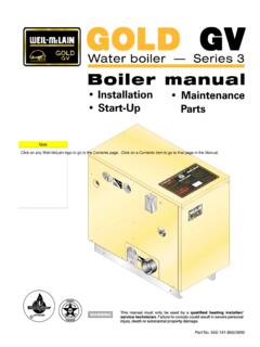
8 12 cycle asymmetric rms (min.) 12 cycle max. peak (min.) Withstand Voltage ( s) To earth and between phases Across open contacts (isolating distance)kVkV170195170195170195 Power Frequency (1 Minute) To earth and between phases Across open contacts (isolating distance)kVkV708070807080 Corona (Extinction)kV262626 Temperature Maximum at 630 A C909090 Temp. Rise Above Ambient Air at 630 A (Max.) K505050 Mechanical Life (Minimum Operations)5,0005,0005,0004 catalog Data CA800005 ENEffective June 2015 Four-position sectionalizing loadbreak 3. Lint illusoraoiNn wioh dimtnsiNns Nf stcoiNnalizing swioch wioh Ring-MNuno Sysotm. NNotse:1. Dimensions given in Figure 3 and Table 3 are for reference Handle can be used on 14 gauge .075 inch ( mm) to.
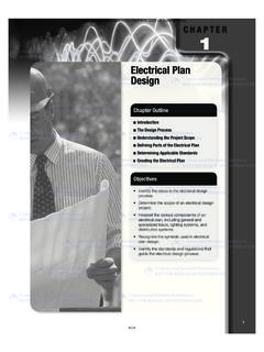
9 25 inch ( mm) thick frontplate. 14 gauge Optional padlock handle is available. (See Table 6, Figure 6.)( mm) ALL LINE CONNECTIONS( mm) HOLE( mm) ( mm) ( mm) ( mm)TANK ( mm)TYPSEE NOTE 3 ARCBARRIERLOCKING NUTFURNISHED WITH ( mm)FNO OUTER (LARGE) RINGFOR SINGLE-PHASE SWITCHD imensional informationTablt 3. DimtnsiNnal InfNrmaoiNn fNr Figurts 3 and 4 (inchts/mm)No. ofDecks/PhaseskV ratings & Blade TypeABCDEFH orizontalMountVertical "204 "338 mm "182 "315 "19 "152 "215 "348 "307 "442 "104 "182 "315 "19 "152 "318 "450 mm312 kA T-Blade12 & 16 kASelector,Straight, & "411 "546 "104 "104 "182 "315 "19 "152 "419 "551 mm316 kA T-Blade "424 mm "104 "104 "192 mm "19 mm "429 mm 5 catalog Data CA800005 ENEffective June 2015 Four-position sectionalizing loadbreak 5 HNlt and wtld pin plactmtno (Ring-MNuno sysotm).
10 * Exterior mounting surface must be flat within .010" ( mm) over entire area.** Interior mounting surface must be clear of 4. Lint illusoraoiNn wioh dimtnsiNns Nf stcoiNnalizing swioch wioh vtr oical Ring-MNuno. (Sidt vitw Nnly, rtf tr oN Figurt 3 fNr FrNno Vitw.)NNotse: 1. Dimensions given in Figure 4 and Table 3 are for reference only. 2. Handle can be used on 14 gauge .075 inch ( mm) to .25 inch ( mm) thick frontplate. 14 gauge shown. 3. Optional padlock handle is available. (See Table 6, Figure 6.)FSEE NOTES 3+3 LOCKING NUTFURNISHED WITH SWITCHTANK ( mm)X = 36Y = 0ON EXTERIOR WALL: .312" DIAMETER X 625" LONG (8 mm) (16 mm)(4) WELD PINSEXTERIOR MOUNTING SURFACE MUST BEFLAT WITHIN .010 OVER ENTIRE AREA. INTERIOR MOUNTING SURFACE MUSTBE CLEAR OF "(4 mm)** "(76 mm) "(38 mm) "(76 mm) "(38 mm) "(17 mm)DIAMETER "(51 mm)*DIAMETER "(159 mm) " MIN.