Transcription of Fractional/Integer-N PLL Basics - Texas Instruments
1 Technical BriefSWRA029 Wireless Communication Business UnitAugust 1999 Fractional/Integer-N PLL BasicsEdited by Curtis BarrettWireless Communication Business UnitAbstract Phase Locked Loop (PLL) is a fundamental part of radio, wireless and telecommunicationtechnology. The goal of this document is to review the theory, design and analysis of PLLcircuits. PLL is a simple negative feedback architecture that allows economicmultiplication of crystal frequencies by large variable numbers. By studying the loopcomponents and their reaction to various noise sources, we will show that PLL isuniquely suited for generation of stable, low noise tunable RF signals for radio, timing andwireless of the main challenges fulfilled by PLL technology are economy in size, power andcost while maintaining good spectral document details basic loop transfer functions, loop dynamics, noise sources andtheir effect on signal noise profile, phase noise theory, loop components (VCO, crystaloscillators, dividers and phase detectors) and principles of integer-N and fractional-Ntechnology.
2 The approach will be mainly heuristic, with many design document is written for designers, technicians and project managers. Designprocedures, equations, performance interpretation, CAD and examples are included tohelp those who have little experience. A list of reference books and articles is BriefSWRA029 Fractional/Integer-N PLL Basics2 ContentsIntroduction to Phase Locked Loop (PLL) ..4 Frequency Synthesis ..5 Digital PLL Synthesis ..5 PLL Components ..8 Voltage Controlled Oscillators (VCO)..8 Phase Frequency Detectors (PFD) .. Filter ..14 The Simple Math of Loop Analysis ..15 Loop Transfer Function ..17 Loop Filter Design ..17 Natural Frequency and Loop Loops and Charge Time and Speed Up ..23 Loop Order and Type ..24 Loop Stability and Phase Margin ..24 Active and Passive Loops ..26 Integer-N Operation.
3 29 Functional Description ..29 Advantages and Limitations ..31 Fractional-N PLL .. Description ..32 Divider Dynamics ..32 Fractional Accumulator ..33 Fractional Spurious Signals and Compensation ..34 Advantages and and Conversions ..41 Division and Multiplication Noise Measurements ..43 The Noise Distribution Function L(fm)..44 Noise Sources in PLL ..44 Spurious Suppression ..46 Reference Spurious Signals ..46 Fractional Spurious Signals ..47 Spurious Signal Suppression ..47 The Effect of Phase Noise on System Performance ..47 Loop Response Simulation ..48 Multi-Loop Design ..48 Measurements Techniques ..49 Phase Signals ..50 Switching Speed ..50 The TI Family of PLL and FAQ ..52 Glossary ..53 References and Further Reading ..54 Technical BriefSWRA029 Fractional/Integer-N PLL Basics3 FiguresFigure 1. General Transceiver Block Diagram.
4 4 Figure 2. Integer-N (classical) PLL Block Diagram ..5 Figure 3. L-Band VCO Schematics ..9 Figure 4. Oscillator Open Loop Gain Model ..10 Figure 5. Oscillator Open Loop Phase Model ..10 Figure 6. Phase Frequency Detector 7. Phase Detector Output (Voltage, Current) Waveforms, for Fv/N<Fr ..12 Figure 8. Phase Detector Timing Waveforms ..12 Figure 9. Programmable Divider Using Dual Modulus ..14 Figure 10. 2nd Order Loop Transfer Function. x = ..19 Figure 11. 2nd Order Error Transfer Function. x = ..19 Figure 12. BL Function of x (j = 100x) ..20 Figure 13. Active 2nd Order Loop 14. Passive 2nd Order Loop Filters ..20 Figure 15. Loop Filter for Current Source (Charge Pump) Phase 16. Open Loop Phase of a 3rd Order Loop ..25 Figure 17. Open Loop Gain of a 3rd Order 18. Integer-N PLL Circuit Detail ..28 Figure 19.
5 Fractional-N Accumulator (will change N to M) ..33 Figure 20. Fractional Spurious: Accumulator Only (2p Jumps Broken Line) and Analog Compensation(Straight Broken Line)..36 Figure 21. Fractional-N PLL - TI Model TRF2050 ..37 Figure 22. Fractional-N Phase Detector Ripple for 3/8 Channel ..38 Figure 23. Main PHP and Compensation Charge Pump Fractional-N Waveforms for 3/8 Channel ..38 Figure 24. Crystal and Phase Detector Noise Transfer Function, N=1000 ..45 Figure 25. VCO Noise Transfer Function ..45 Figure 26. PLL Composite Phase Noise ..46 Figure 27. Mix and Count-Down Dual 28. Delay-Line Phase Noise 29. Dual Synthesizer Using 1. Typical Q for Inductors and Varactors in the 800-2000 MHz Range ..9 Table 2. Bit Weighting in a Binary Accumulator ..35 Table 3. Short Summary of TRF2050 Parameters ..40 Technical BriefSWRA029 Fractional/Integer-N PLL Basics4 Introduction to Phase Locked Loop (PLL)Until DSP technology is capable of directly processing and generating the RF signalsused to transmit wireless data, traditional RF engineering will remain a fundamental partof wireless communication systems design.
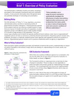
6 As it stands, wireless transceivers must stillbe able to generate a wide range of frequencies in order to upconvert the outgoing datafor transmission and downconvert the received signal for processing (see Figure 1).Figure 1. General Transceiver Block DiagramAlthough there are a variety of frequency synthesis techniques, phase locked loop (PLL)represents the dominant method in the wireless communications industry. PLL, like mostwireless communication technologies, is relatively new and has matured only in the lastdecade. The ability to execute all PLL functions on a single integrated circuit (IC) hascreated an economical, mass production solution to meet the needs of industry. CurrentPLL ICs are highly integrated digital and mixed signal circuits that operate on low supplyvoltages and consume very low power. These ICs require only an external crystal (Xtal)reference, voltage controlled oscillators (VCO), and minimal external passivecomponents to generate the wide range of frequencies needed in a moderncommunications transceiver.
7 Although a proven technology, PLL is still changing andevolving to keep pace with the wireless BriefSWRA029 Fractional/Integer-N PLL Basics5 The problems associated with operating a wireless communications system havebecome especially acute in the last few years with the advance of cellular telephony andthe emergence of wireless data networks. Because there are more users now, mostoperating at progressively higher data rates, both interference and signal-to-noise-ratiohave become key considerations in system design. Phase noise and spurious emissionscontribute significantly to both of these issues and are largely dependent on theperformance of the PLL IC. Minimizing phase noise and spurs of the frequencysynthesizer while staying within power consumption, size, and cost restraints is one ofthe challenges for today s RF design engineers.
8 We will see later how an emerging PLLtechnology called fractional-N synthesis has made this task more purpose of this document is to illustrate practical PLL signal generation techniques,review PLL basic building blocks, explain various phase noise sources and theirmeasurement, and compare integer-N and fractional-N PLL technologies. The focus willbe on basic principles, synthesis parameters, phase noise and its measurement, as wellas design trade-off. This document is intended for design, system, and test engineers aswell as technicians and technical SynthesisFrequency Synthesis is the engineering discipline dealing with the generation of multiplesignal frequencies, all derived from a common reference or time base. The time baseused is typically a Temperature Compensated Crystal Oscillator (TCXO). The TCXO provides a reference frequency to the synthesizer circuit so that it may accuratelyproduce a wide range of signals that are stable and relatively low in phase PLL SynthesisAmong the many different frequency synthesis techniques, the dominant method used inthe wireless communications industry is the digital PLL circuit.
9 While there are somebenefits to using other synthesis techniques, they are outside the scope of this documentand will not be discussed PLLC ompared to the analog techniques used in the infancy of frequency synthesis, themodern PLL is now a mostly digital circuit. Figure 2 shows a typical block diagram of aPLL implemented with a TCXO 2. Integer-N (classical) PLL Block DiagramTechnical BriefSWRA029 Fractional/Integer-N PLL Basics6 This traditional digital PLL implementation will be termed integer-N to avoid confusiondue to the addition of fractional-N technology. The PLL circuit performs frequencymultiplication, via a negative feedback mechanism, to generate the output frequency,Fvco, in terms of the phase detector comparison frequency, = N Fr(Equation 1)To accomplish this, a reference frequency must be provided to the phase , the TCXO frequency (Fx), is divided down (by R) on-board the PLL IC.
10 Thephase detector utilizes this signal as a reference to tune the VCO and, in a locked state, it must be equal to the desired output frequency, Fvco, divided by / N = Fx / R = Fr(Equation 2)Thus, the output frequency that the synthesizer generates, Fvco, can be changed byreprogramming the divider N to a new value. By changing the value N, the VCO can betuned across the frequency band of interest. The only constraint to the frequency outputof the system is that the minimum frequency resolution, or minimum channel spacing, isequal to spacing = Fvco / N = Fr(Equation 3)When the PLL is in unlocked state (such as during initial power up or immediately afterreprogramming a new value for N) the phase detector will create an error voltage basedon the phase difference of the two input signals. This error voltage will change the outputfrequency of the VCO so that it satisfies Equation 2.