Transcription of Future Compressor Station Technologies and Applications
1 Future Compressor Station Technologies and ApplicationsJason GatewoodSouthwest Research InstituteFeb 9th, 2012 Gas Electric Partnership ConferenceOverview Review of Historical Compression Applications Three Compressor Station technology/application trends that may be more prevalent in the Future Technology/application Trend 1: Significant increase in Waste Heat Recovery Technology/application Trend 2: Coordinated Energy Power Systems Technology/application Trend 3: CO2compression using integrated high speed EMD compressors (with an introduction to Future CO2compression needs)Compression Applications in the USOil & Gas Compression US Market Upstream Mostly small high speed separable recips for gas gathering and push compression.
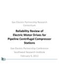
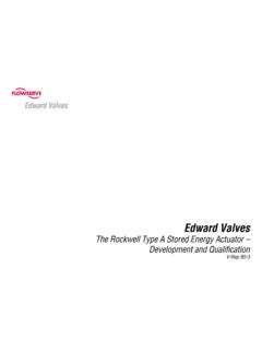
2 Some gas turbine s for pull compressions (typically less than 10kHp) Limited electrical infrastructure available Downstream Midsize and large steam turbine driven compressors Low speed recips Some gas turbines Midstream 40-50% low speed integral recips 20-30% industrial and aeroderivative gas turbines 10-15% high speed separables (both gas engine and electrical) 5% electric motor driven centrifugalsMap of US Compressor Stations (2008)Over 900 interstate pipeline compression stations in the USMajor Interstate PipelineCompressor Stations in USColumbia Gulf/Gas Transmission (NiSource) 170 Northern Natural Gas (MidAmerican Holdings) 125 Tennessee Gas (El Paso Corporation) 85 Williams Natural Gas (Williams Companies) 77 Texas Eastern Transmission (Spectra) 75 Natural Gas Pipeline Company (Kinder Morgan) 72 El Paso Natural Gas (El Paso Corporation) 64 Noram (Arkla Gas, Center Point Energy-HL&P) 52 Consolidated Natural Gas (Dominion) 52 ANR (Transcanada) 50 Southern Natural Gas (El Paso Corporation) 50 KN Energy (Kinder Morgan) 48 Transco (Williams Companies) 46 Panhandle Eastern (Southern Union) 42 CIG (El Paso Corporation) 35 Trunkline (Southern Union)
3 32 Koch 28 Minimum of 3,700,000 hp must be replaced in next 15 years on interstate pipelines. Pipeline Compression History:Horizontal Compressor Original pipeline prime mover first installed in the 1930s. Internal combustion spark ignited, four cylinder unit (1700 bhp supercharged) running at 125 rpm. Power cylinders are horizontal-opposing. Most of these units (Cooper and Worthington) have been replaced with integral horsepower Some remain in operation with Tennessee Gas, Northern Natural and Panhandle Eastern.
4 Pipeline Compression History:Gas Integral Compressors Internal combustion, spark ignited, engine driver with integral reciprocating Compressor (the engine and Compressor share the same crankshaft). Majority of these units were installed from the 1950-1970. Integrals are still a workhorse for the natural gas compression industry. Units are either 2 or 4 cycle and are typically supercharged. Horsepower ranges 600 - 17,000 bhp. Manufacturers have included Cooper-Bessemer, Dresser Rand, Ingersoll Rand, Worthington and Clark. Massive in size, complex auxiliary systems, costly to operate. Excellent efficiencies above 40%.
5 Pipeline Compression History:Gas Separable Compressors The engine and Compressor have individual crankshafts and are coupled as separate devices on a unitized skid. Introduced late 1960s and still major market player. Initially suffered as they were high speed machines (350 - 1200 rpms) with unacceptable vibrations. Recent years made a come back and are now displacing some of the larger integral units. Pipelines purchase primarily Ariel Compressors through packagers . Other vendors are GE, Cameron, and Compression History:Gas Turbine Driven Centrifugals Industrial Gas Turbines are currently the prime mover of choice for many mainline Applications .
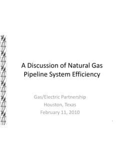
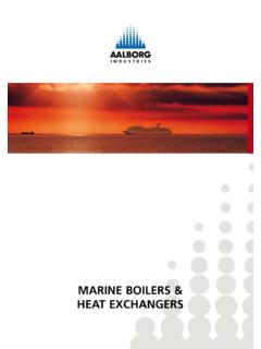
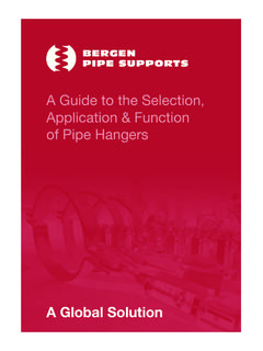
6 Gas Turbines are more reliable than internal combustion engines, have very low maintenance costs and are basically clean burn units (low emissions). Relatively low efficiency of 30% to 36% (compared to integrals). The original gas turbines (1960s-1970s) were classified as aero derivative machines and are typically jet engine platforms converted to drive a centrifugal Compressor . Later industrial gas turbines were introduced. Gas turbine units are normally used for higher horsepower ( ,000 bhp) Applications . Most US Applications use Solar. Other manufacturers are Siemens and Compression History:Other Equipment Configurations Fixed Low Speed Electric Reciprocating Fixed Medium Speed Electric Reciprocating VFD Reciprocating Conventional Fixed-Speed Electric Centrifugal Conventional Fixed Speed with Voith VoreconHydrodynamic Fluid Coupling Conventional Speed VFD-Centrifugal Screw compressors and other PD compressors Voith VoreconPipeline Operating Conditions25,00020,00015,00010,0005,0002 ,0003,0004,0005,0006,000 INLET VOLUME FLOW74%82%85%78%85%82%86%Pipeline Resistance Curve1,000 The operating map based on the design courtesy of Solar TurbinesReality!
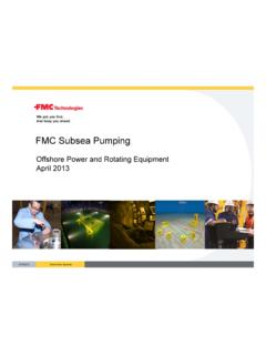
7 -500005000100001500020000250003000035000 400000500010000150002000025000 ACFMHEAD (FT)1 UNIT2 UNITS3 UNITS IN PARALLELSITE POWER AT 75 FHow the Compressor ends up courtesy of Solar TurbinesPart Speed and Part Load Operation is CriticalPipeline Compression Selection Criteria Ease of maintenance Emissions Operating flexibility and range Reliability/Availability Total Installed Cost Fuel Efficiency Legislation (particularly for CO2) Future Pipeline Compression Opportunities Numerous Technologies available or being developed to address industry needs! This presentation only covers a few particularly interesting options are certainly feasible!
8 (Disclaimer) Three Technologies / Applications trends that maybe more prevalent in the Future Waste Heat Recovery Coordinated Energy Power Systems Use of integrated high speed EMD compressors for CO2compression Technology/Application Trend 1: Significant Deployment of Waste Heat RecoveryWHR Recent Development Summary SwRI conducted industry sponsored research on WHR technology development In 2010, 20 small scale WHR concepts for use at a pipeline Station were identified Initial technical evaluations were completed for each of the 20 concept The concepts were ranked based on metrics and pipeline company feedback Further analysis was completed on the top 5 concepts2010 WHR Development Summary The top ten WHR concepts based on the scoring matrix are below (bolded concepts were top five selected based on matrix rankings and pipeline company feedback)1.
9 Process Gas Drying2. Turbine Inlet Cooling3. Fuel Gas Pre-Heating4. Electricity Use at Station (Stacked Rankine)5. Pipeline Gas Pre-Cooling6. Heat Storage7. Gas Treatment using Waste Heat8. Thermoelectrics9. Industrial Process (co-locating) Cycle for Added Compression2011 WHR Project Objective: Further evaluate and develop 3 WHR concepts Pipeline gas cooling Stacked Rankine Cycle (SRC) Heat storage Pipeline gas cooling and SRC Develop conceptual design of WHR concepts Identify commercial equipment which can be used for concept Complete economic analysis on WHR concept at idealized Station Heat storage Evaluate use of different types of thermal energy storage (TES)
10 At pipeline stations Identify the TES method that should be used with various WHR concepts Design heat storage system which can be used with pipeline gas cooling conceptPipeline Gas Cooling General Concept Use waste heat to perform industrial chilling Used chilling to cool gas before compression Lower energy to compress cooler gas, or Compress more gas with same energyThermal Energy Storage (TES) -General Concept Store thermal energy from gas compression waste heat in the form of heat to use for various processes and systems Sensible, Latent and Bond Energy Storage Methods Implementation withpipeline gas cooling Auxiliary Heater System startup andintermissionWaste Heat Capture SystemStorage Tank for Storage MediumPipeline Gas Cooling/Absorption ChillerCompressor/ TurbineStacked Rankine Cycle General Concept Waste heat drives an organic Rankine cycle (ORC) to produce electrical power Multiple heat sources available at different grades Exhaust @ 500 C: 70% Water Jacket @ <100 C: 20% Aftercooler @ < 60 C.