Transcription of G4A - Omron
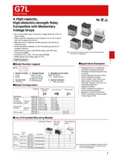
1 1G4AG4 APCB Power RelayMiniature Single-pole Relay with 80A Surge Current and 20A Switching Current Capable of Switching Motor Load of 80-A Surge Current and 20A Switching/Cut-off Current miniature , relay with high switching power and long endurance. Creepage distance conforms to UL and CSA standards. Highly noise-resistive insulation materials employed. Standard model available with flux protection Compliant Model Number LegendG4A-@@-@-@ 12 3 41. Number of Poles1: 1-pole2. Contact FormA: SPST-NO (1a) Application Examples Air conditioner3. Terminal ShapeNone : #250 quick-connect/PCB coil terminalsP : PCB terminals/PCB coil terminals4.
2 Special FunctionE: For long endurance CharacteristicsNote. The data given above are initial values.* conditions: 5 VDC, 1 A, voltage drop method.* conditions: The insulation resistance was measured with a 500 VDC megohmmeter at the same locations as the dielectric strength was measured.* value was measured at a switching frequency of 120 resistance *1100 m time20 ms time10 ms operating frequencyMechanical18,000 operations/hrInsulation resistance *21,000 M min. Dielectric strengthBetween coil and contacts4,500 VAC 50/60 Hz for 1minBetween contacts of the same polarity1,000 VAC 50/60 Hz for 1minImpulse withstand voltageBetween coil and kV ( x 50 s)Insulation distanceBetween coil and contactsClearance: mm,Creepage: mmVibration resistanceDestruction10 to 55 to 10 Hz, mm single amplitude ( mm double amplitude)Malfunction10 to 55 to 10 Hz, mm single amplitude ( mm double amplitude)Shock resistanceDestruction1,000 m/s2 Malfunction200 m/s2 DurabilityMechanical2,000,000 operations min.
3 (at 18,000 operations/hr)Resistive load100,000 operations min.(ON/OFF: 1 s)Motor load200,000 operations min.(ON/OFF: s)Inverter load30,000 operations min.(ON: 3 s, OFF: 5 s)Failure rate (P level) (reference value *3)100 mA at 5 VDCA mbient operating temperature-20 C to 60 C (with no icing or condensation)Ambient operating humidity 5% to 85%WeightApprox. 23 g Ordering Information Quick-connect/PCB coil terminals PCB terminals Ratings CoilNote 1. The rated current and coil resistance are measured at a coil temperature of 23 C with a tolerance of 10%. 2. The inductances shown above are reference Operating characteristics are measured at a coil temperature of 23 Max.
4 Permissible voltage refers to the maximum value in a varying range of operating power voltage, not a continuous voltage. ContactsContact formLoad Contact TerminalCoil terminalModelRated voltageMinimum packing unitSPST-NO (1a)#250 quick-connect terminalsPCB terminalsG4A-1A-E12, 24 VDC50 pcs/trayContact formLoad Contact TerminalCoil terminalModelRated voltageMinimum packing unitSPST-NO (1a)PCB terminalsPCB terminalsG4A-1A-PE12, 24 VDC50 pcs/trayItemRated voltageRated current(mA)Coil resistance( )Must operate voltage(V)Must release voltage(V)Max. permissible voltage(V)Power consumption(W)% of rated voltage12 VDC7516070% (at 23 C) loadContact typeSingleContact materialAg-Alloy (Cd free)Rated load20 A at 250 VACR ated carry current20 AMax.
5 Switching voltage250 VACMax. switching current20 ANote. When ordering, add the rated coil voltage to the model : G4A-1A-E DC12 However, the notation of the coil voltage on the product case as well as on the packing will be markedas @@ coil voltage Motor Ratings Inverter Ratings Overload Durability (Reference Value)Load conditionsSwitching frequencyElectrical durability250 VAC:Inrush current: 80 A, s (cos = )Break current: 20 A (cos = )ON: sOFF: s200,000 operationsLoad conditionsSwitching frequencyElectrical durability100 VAC:Inrush current: 200 A ( )Break current: 20 AON: 3 sOFF: 5 s30,000 operationsLoad conditionsSwitching frequencyElectrical durability250 VAC:Inrush current.
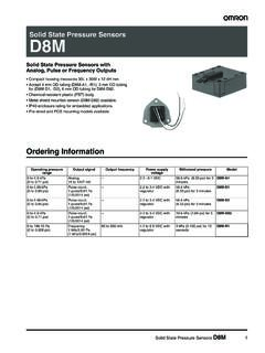
6 80 ABreak current: 80 A (cos = )ON: sOFF: 99 s1,500 operations2G4 APCB Power RelayG4A Engineering Data Dimensions Maximum Switching CapacityG4A-1A-(P)E DurabilityG4A-1A-(P)E Ambient Temperature vs. Maximum Coil VoltageG4A-1A-(P)E Ambient Temperature vs. Must Operate and Must Release Voltages G4A-1A-(P)E Shock MalfunctionG4A-1A-(P)ENumber of Relays: 5 pcsNote. The maximum coil voltage is the maximum voltage that can be applied to the relay conditions: Shock is applied in X, Y, Z directions three times each with and without energizing the Relays to check the number of :200 m/s2 Switching current (A)Switching voltage (V)1007050301075311 3 5 10 30 50 100 300 500 1,000AC loadDurability (x 104 operations)250 VAC resistive loadSwitching current (A)2520151050100908070605040302010 Maximum coil voltage (%)Ambient temperature ( C)-25 0 10 20 30 40 50 60 70 80180160140120100800 Must operate and must release voltage (ratio of rated voltage) (%)Ambient temperature ( C)100806040200-60 -40 -20 0 20 40 60 80 100 Sample.
7 G4A-1A-E DC12 VNumber of Relays: 5 pcsMust Operating voltageMust Recovery voltageZZZ'Z'Shock directionUnit: m/s2 YYY'Y'XXX'X'1,0001,0001,0001,0001,0001,0 00200400600600400200800800contact AFour, + dia. 012 max.( )* max.( )* max.( )*341234* Average valueTab TerminalPCB Terminal#250 quick-connect/PCB coil terminalsG4A-1A-ETerminal Arrangement/Internal Connections(Top View) (Bottom View)Mounting Holes (Bottom View)(No coil polarity)Four, + dia. 012 max.( )* max.( )* max.( )*1234* Average valueStraight PCB/PCB coil terminalsG4A-1A-PEPCB Mounting Holes(Bottom View)(No coil polarity)Terminal Arrangement/Internal Connections(Bottom View)3G4 APCB Power RelayG4A Approved Standards The rated values approved by each of the safety standards may be different from the performance characteristics individually defined in this datasheet.
8 Precautions Please refer to PCB Relays Common Precautions for correct Recognized (File No. E41643) CSA Certified (File No. LR31928) EN/IEC, VDE Certified (Certificate No. 107293) ModelNumber of polesCoil ratingsContact ratingsNumber of test operationsG4A-1A-EG4A-1A-PESPST-NO(1a)12 to 24 VDC20 A, 250 VAC (Resistive) 40 C100,00015 A, 30 VDC (Resistive) 40 C23 A, 277 VAC (General Purpose) 40 C30,000TV-15 120 V AC 40 C25,000 ModelNumber of polesCoil ratingsContact ratingsNumber of test operationsG4A-1A-EG4A-1A-PESPST-NO(1a)12 to 24 VDC20 A, 250 VAC (Resistive) 40 C10,00015 A, 30 VDC (Resistive) 40 C23 A, 277 VAC (General Purpose) 40 C30,000TV-15 120 V AC 40 C25,000 ModelNumber of polesCoil ratingsContact ratingsNumber of test operationsG4A-1A-EG4A-1A-PESPST-NO(1a)12 , 24 VDC20 A, 250 VAC (cos = )
9 50 C100,000 Mounting When mounting more than two Relays side by side, keep a 3 mm gap horizontally and vertically between Relays to ensure a good heat dissipation. It may cause a malfunction if heat is not dissipated smoothly from the Relay. Terminals The terminals fit FASTON receptacle 250 and are suitable for positive-lock mounting. Use only Faston terminals with the specified leads for connecting Faston receptacles with wire diameters that are within the allowable range for the load current. Do not apply excessive force to the terminals when mounting or dismounting the Faston receptacle. Insert and remove terminals carefully one at a time.
10 Do not insert terminals at an angle, or insert/remove multiple terminals at the same to the following table for recommendations of connectors made by Omron . Other Precautions This Relay is suitable for power load switching of air-conditioning compressors and power supplies, etc. Do not use the G4A to switch micro loads less than 100 mA, such as in signal UseTy p eReceptacle terminalsHousing#250 terminals (width: mm)XT3W-S441-12XT3W-S442-12XT3W-S443-12X T3B-1S white4G4 APCB Power RelayG4A Application examples provided in this document are for reference only. In actual applications, confirm equipment functions and safety before using the product.