Transcription of G5V-2 - Omron
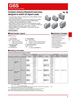
1 G5V-2 . Low Signal Relay General-purpose, Low-cost, Two-pole Relays for Signal Circults General-purpose DIL terminal layout. Wide switching power of 10 A to 2 A. Fully-sealed type Relays standardized with bifurcated crossbar contacts. Highly reliable in addition to its high environment resistance. Conforms to FCC Part 68 (impulse withstand voltage of 1,500 V for 10 x 160 s between coil and contacts and between contacts of the same polarity). High dielectric strength at 1,000 VAC between coil and contacts, and 750 VAC. between contacts of the same polarity. UL and CSA standard approved. RoHS Compliant Model Number Legend Application Examples G 5 V-@- @ 1.
2 Number of Poles/ Contact form 2. Classification Telecommunication equipment 2: 2-pole/DPDT (2c) None: Standard Security equipment 1 2. H1: High-sensitivity Ordering Information Characteristics G. 5. Minimum Item Classification Standard High-sensitivity V. Enclosure Contact Terminal Rated coil - Model packing Classification rating form shape voltage unit Contact resistance *1 50 m max. 100 m max. 2. Operate time 7 ms max. 3 VDC. Release time 3 ms max. 5 VDC. Insulation resistance *2 1,000 M min. (at 500 VDC). 6 VDC. Between coil and Standard G5V-2 9 VDC 1,000 VAC, 50/60 Hz for 1 min contacts 12 VDC Dielectric Between contacts 750 VAC, 50/60 Hz 500 VAC, 50/60 Hz for Fully DPDT PCB 25.
3 24 VDC strength of the same polarity for 1 min 1 min sealed (2c) terminals pcs/tube 48 VDC Between contacts 1,000 VAC, 50/60 Hz for 1 min 5 VDC of different polarity Between coil and High- 12 VDC 1,500 V (10 x 160 s). G5V-2 -H1 contacts sensitivity 24 VDC Impulse Between contacts 48 VDC withstand 1,500 V (10 x 160 s). of the same polarity voltage Note: When ordering, add the rated coil voltage to the model number. Between contacts 1,500 V (10 x 160 s). Example: G5V-2 DC3. of different polarity Rated coil voltage 10 to 55 to 10 Hz, mm single amplitude Destruction However, the notation of the coil voltage on the product case as well as Vibration ( mm double amplitude).
4 On the packing will be marked as @@ VDC. resistance 10 to 55 to 10 Hz, mm single amplitude Malfunction ( mm double amplitude). Shock Destruction 1,000 m/s2. resistance Malfunction 200 m/s2 100 m/s2. 15,000,000 operations min. Mechanical (at 36,000 operations/hr). Durability AC: 100,000 operations 100,000 operations min., DC: 300,000. Electrical min. (at 1,800. operations min. operations/hr). (at 1,800 operations/hr). Failure rate (P level) (reference 10 A at 10 m VDC. value) *3. -25 C to 65 C -25 C to 70 C. ambient operating temperature (with no icing or (with no icing or condensation) condensation). ambient operating humidity 5% to 85%. Weight Approx.
5 5 g Note: The above values are initial values. *1. The contact resistance was measured with 10 mA at 1 VDC with a voltage drop method. *2. The insulation resistance was measured with a 500 VDC megohmmeter applied to the same parts as those used for checking the dielectric strength. *3. This value was measured at a switching frequency of 120 operations/min and the criterion of contact resistance is 50 . This value may vary depending on the switching frequency and operating environment. Always double-check relay suitability under actual operating conditions. 1. G5V-2 Low Signal Relay Ratings Coil Contacts Must Must Classification Standard High-sensitivity Max.
6 Rated Coil operate release Power Load Resistive load Rated voltage Classification current resistance voltage voltage consumption Contact type Bifurcated crossbar voltage (V). (mA) ( ) (V) (V) (mW) Contact material Ag + Au-alloy % of rated voltage A at 125 VAC; A at 125 VAC;. 3 VDC 18 Rated load 2 A at 30 VDC 1 A at 24 VDC. 5 VDC 100 50 Rated carry current 2A. 6 VDC 72 Max. switching voltage 125 VAC, 125 VDC. 75% 5% 120% Approx. 500. Standard 9 VDC 162 Max. switching current 2A 1A. max. min. (at 23 C). 12 VDC 288. 24 VDC 1,152. 48 VDC 12 4,000 Approx. 580. 5 VDC 30 180% Approx. 150. 12 VDC 960. High- 75% 5% (at 23 C). 24 VDC 2,880 Approx. 200. sensitivity max.
7 Min. 150%. 48 VDC 7,680 Approx. 300. (at 23 C). Note 1. The rated current and coil resistance are measured at a coil temperature of 23 C with a tolerance of 10%. 2. Operating characteristics are measured at a coil temperature of 23 C. 3. The maximum voltage is the highest voltage that can be imposed on the relay coil. Engineering Data G Maximum Switching Capacity Durability 5. V Standard/ G5V-2 High-sensitivity/ G5V-2 -H1 Standard/ G5V-2 High-sensitivity/ G5V-2 -H1. - 5 100. Switching current (A). Durability (x104 operations). 2. Switching current (A). 5 100. Durability (x104 operations). 24 VDC resistive load 3 50 50. 2 30 VDC resistive load AC resistive load 30 30.
8 1 1 AC resistive load 125 VAC resistive load 10 10. DC resistive load 5 125 VAC resistive load 5. DC resistive load 3 3. 1 1. 0 10 30 50 100 300 500 0 10 30 50 70 125 300 500 0 1 2 3 1 Switching voltage (V) Switching voltage (V) Switching current (A) Switching current (A). ambient Temperature vs. Maximum Coil Voltage Standard/ G5V-2 High-sensitivity/ G5V-2 -H1. 160. Maximum coil voltage (%). 200. Maximum coil voltage (%). 3 to 24 VDC. 180. 140. 3 to 24 VDC. 160. 120. 140. 100. 120. 48 VDC 48 VDC. 80. 100. 60. 80. 0 20 40 60 80 100 120 0 20 40 60 80. ambient temperature ( C) ambient temperature ( C). Note: The maximum coil voltage refers to the maximum value in a varying range of operating power voltage, not a continuous voltage.
9 ambient Temperature vs. Must Operate or Must Release Voltage Shock Malfunction Standard/ G5V-2 High-sensitivity/ G5V-2 -H1 Standard/ G5V-2 High-sensitivity/ G5V-2 -H1. 100 100 Y Y. On the basis of rated voltage (%). On the basis of rated voltage (%). Sample: G5V-2 Sample: G5V-2 -H1 1,000 1,000. Number of Relays: 10 pcs Number of Relays: 10 pcs max. 800 800. max. 80 80 X. X 600 600. min. min. X Z X Z. 1,000 400 1,000 1,000 400 1,000. 60 60 200 200. max. 200 200. 40 40 X. max. min. 1,000 400 De- 1,000 1,000 400 De- 1,000. energized energized X Z' X' Z' X'. min. 600 600. 20 20 800 Shock direction 800. Shock direction X X' Energized X X' Energized Must operate voltage Must operate voltage 1,000 1,000.
10 Y Y' Y Y'. Must release voltage Must release voltage Z. 0 0 Z Unit: m/s2 Unit: m/s2. -60 -40 -20 0 20 40 60 80 100 120 -60 -40 -20 0 20 40 60 80 100 120 Sample: G5V-2 12 VDC Z' Sample: G5V-2 -H1 12 VDC. Z' Y'. Y' Number of Relays: 10 pcs Number of Relays: 10 pcs ambient temperature ( C) ambient temperature ( C). Conditions: Shock is applied in X, Y, and Z directions three times each with and without energizing the Relays to check the number of contact malfunctions. 2. G5V-2 Low Signal Relay Dial Pulse Test (with Must Operate and Must Release Voltage) *1 Dial Pulse Test Contact Reliability Test *1, *2. Standard/ G5V-2 (Contact Resistance) *1 Standard/ G5V-2 High-sensitivity/ G5V-2 -H1.