Transcription of G5V-2 - Omron
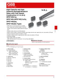
1 G5V-2 . Low Signal Relay General-purpose, Low-cost, Two-pole Relays for Signal Circults General-purpose DIL terminal layout. Wide switching power of 10 A to 2 A. Fully-sealed type Relays standardized with bifurcated crossbar contacts. Highly reliable in addition to its high environment resistance. Conforms to FCC Part 68 (impulse withstand voltage of 1,500 V for 10 x 160 s between coil and contacts and between contacts of the same polarity). High dielectric strength at 1,000 VAC between coil and contacts, and 750 VAC.
2 Between contacts of the same polarity. UL and CSA standard approved. RoHS Compliant Model Number Legend Application Examples G 5 V-@- @ 1. Number of Poles/ Contact form 2. Classification Telecommunication equipment 2: 2-pole/DPDT (2c) None: Standard Security equipment 1 2. H1: High-sensitivity Ordering Information Characteristics G. 5. Minimum Item Classification Standard High-sensitivity V. Enclosure Contact Terminal Rated coil - Model packing Classification rating form shape voltage unit Contact resistance *1 50 m max.
3 100 m max. 2. Operate time 7 ms max. 3 VDC. Release time 3 ms max. 5 VDC. Insulation resistance *2 1,000 M min. (at 500 VDC). 6 VDC. Between coil and Standard G5V-2 9 VDC 1,000 VAC, 50/60 Hz for 1 min contacts 12 VDC Dielectric Between contacts 750 VAC, 50/60 Hz 500 VAC, 50/60 Hz for Fully DPDT PCB 25. 24 VDC strength of the same polarity for 1 min 1 min sealed (2c) terminals pcs/tube 48 VDC Between contacts 1,000 VAC, 50/60 Hz for 1 min 5 VDC of different polarity Between coil and High- 12 VDC 1,500 V (10 x 160 s).
4 G5V-2 -H1 contacts sensitivity 24 VDC Impulse Between contacts 48 VDC withstand 1,500 V (10 x 160 s). of the same polarity voltage Note: When ordering, add the rated coil voltage to the model number. Between contacts 1,500 V (10 x 160 s). Example: G5V-2 DC3. of different polarity Rated coil voltage 10 to 55 to 10 Hz, mm single amplitude Destruction However, the notation of the coil voltage on the product case as well as Vibration ( mm double amplitude). on the packing will be marked as @@ VDC. resistance 10 to 55 to 10 Hz, mm single amplitude Malfunction ( mm double amplitude).
5 Shock Destruction 1,000 m/s2. resistance Malfunction 200 m/s2 100 m/s2. 15,000,000 operations min. Mechanical (at 36,000 operations/hr). Durability AC: 100,000 operations 100,000 operations min., DC: 300,000. Electrical min. (at 1,800. operations min. operations/hr). (at 1,800 operations/hr). Failure rate (P level) (reference 10 A at 10 m VDC. value) *3. -25 C to 65 C -25 C to 70 C. Ambient operating temperature (with no icing or (with no icing or condensation) condensation). Ambient operating humidity 5% to 85%.
6 Weight Approx. 5 g Note: The above values are initial values. *1. The contact resistance was measured with 10 mA at 1 VDC with a voltage drop method. *2. The insulation resistance was measured with a 500 VDC megohmmeter applied to the same parts as those used for checking the dielectric strength. *3. This value was measured at a switching frequency of 120 operations/min and the criterion of contact resistance is 50 . This value may vary depending on the switching frequency and operating environment.
7 Always double-check relay suitability under actual operating conditions. 1. G5V-2 Low Signal Relay Ratings Coil Contacts Must Must Classification Standard High-sensitivity Max. Rated Coil operate release Power Load Resistive load Rated voltage Classification current resistance voltage voltage consumption Contact type Bifurcated crossbar voltage (V). (mA) ( ) (V) (V) (mW) Contact material Ag + Au-alloy % of rated voltage A at 125 VAC; A at 125 VAC;. 3 VDC 18 Rated load 2 A at 30 VDC 1 A at 24 VDC. 5 VDC 100 50 Rated carry current 2A.
8 6 VDC 72 Max. switching voltage 125 VAC, 125 VDC. 75% 5% 120% Approx. 500. Standard 9 VDC 162 Max. switching current 2A 1A. max. min. (at 23 C). 12 VDC 288. 24 VDC 1,152. 48 VDC 12 4,000 Approx. 580. 5 VDC 30 180% Approx. 150. 12 VDC 960. High- 75% 5% (at 23 C). 24 VDC 2,880 Approx. 200. sensitivity max. min. 150%. 48 VDC 7,680 Approx. 300. (at 23 C). Note 1. The rated current and coil resistance are measured at a coil temperature of 23 C with a tolerance of 10%. 2. Operating characteristics are measured at a coil temperature of 23 C.
9 3. The maximum voltage is the highest voltage that can be imposed on the relay coil. Engineering Data G Maximum Switching Capacity Durability 5. V Standard/ G5V-2 High-sensitivity/ G5V-2 -H1 Standard/ G5V-2 High-sensitivity/ G5V-2 -H1. - 5 100. Switching current (A). Durability (x104 operations). 2. Switching current (A). 5 100. Durability (x104 operations). 24 VDC resistive load 3 50 50. 2 30 VDC resistive load AC resistive load 30 30. 1 1 AC resistive load 125 VAC resistive load 10 10. DC resistive load 5 125 VAC resistive load 5.
10 DC resistive load 3 3. 1 1. 0 10 30 50 100 300 500 0 10 30 50 70 125 300 500 0 1 2 3 1 Switching voltage (V) Switching voltage (V) Switching current (A) Switching current (A). Ambient Temperature vs. Maximum Coil Voltage Standard/ G5V-2 High-sensitivity/ G5V-2 -H1. 160. Maximum coil voltage (%). 200. Maximum coil voltage (%). 3 to 24 VDC. 180. 140. 3 to 24 VDC. 160. 120. 140. 100. 120. 48 VDC 48 VDC. 80. 100. 60. 80. 0 20 40 60 80 100 120 0 20 40 60 80. Ambient temperature ( C) Ambient temperature ( C).