Transcription of G7L - Omron
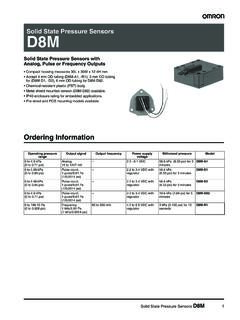
1 1G7LG7 LPower RelayA High-capacity, High-dielectric-strength Relay Compatible with Momentary Voltage Drops No contact chattering for momentary voltage drops up to 50% of rated voltage. Wide-range AC-activated coil that handles 100 to 120 or 200 to 240 VAC at either 50 or 60 Hz. Miniature size for maximum switching power, particularly for inductive loads. Flame-resistance materials (UL94V-0-qualifying) used for all insulation material. Quick-connect, screw, and PCB terminals, and DIN track mounting available . Conforms to UL, CSA, TUV and meets IEC950. Safety design with contact gap of 3 mm. List of E-bracket Mounting ModelsRoHS CompliantMounting E-bracketsDIN Track Mounting AdapterFront-connecting SocketTerminalContact formModelTest buttonQuick-connect terminalsSPST-NOG7L-1A-T : E-bracket (R99-07), Adapter (P7LF-D), Front-connecting socket (P7LF-06) and Cover (P7LF-C) sold With test button DPST-NOG7L-2A-T G7L-2A-TJ With test button Screw terminalsSPST-NOG7L-1A-B G7L-1A-BJ With test button DPST-NOG7L-2A-B G7L-2A-BJ With test button Note.
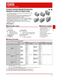
2 Accessories: E-bracket, Adapter, Front-connecting socket and Cover sold separately. Application Examples Compressors for air conditioners and heater switching controllers. Switching controllers for power tools or motors. Power controllers for water heaters. Power controllers for dryers. Lamp controls, motor drivers, and power supply switching in copy machines, facsimile machines, and other office equipment. Lighting controllers. Power controllers for packers or food processing equipment. Magnetron control in microwaves. Power controllers for Uninterruptible Power Supply (UPS) Model Number LegendG7L-@@-@@@ 12 3451. Number of Poles1: 1 pole2: 2 poles2. Contact FormA: Terminal ShapeT: Quick connect terminals (#250)B: Screw terminalsP: PCB terminals4. Mounting ConstructionBlank: E-bracketUB : Upper bracket5. Special FunctionsJ: With test button Model ConfigurationTerminalQuick-connect terminalsScrew terminalsPCB terminalsClassificationContact formE-bracket mounting (E-bracket is sold separately) SPST-NOG7L-1A-TG7L-1A-B DPST-NOG7L-2A-TG7L-2A-B With test buttonSPST-NOG7L-1A-TJG7L-1A-BJ DPST-NOG7L-2A-TJG7L-2A-BJ Upper bracket mounting SPST-NOG7L-1A-TUBG7L-1A-BUB DPST-NOG7L-2A-TUBG7L-2A-BUB With test buttonSPST-NOG7L-1A-TUBJG7L-1A-BUBJ DPST-NOG7L-2A-TUBJG7L-2A-BUBJ PCB mounting SPST-NO G7L-1A-PDPST-NO G7L-2A-P2G7 LPower RelayG7L Ordering InformationE-bracket/Adapter/Socket MountingQuick-connect TerminalUpper Bracket MountingQuick-connect TerminalE-bracket/Adapter MountingScrew TerminalUpper Bracket MountingScrew TerminalPCB MountingDIN Track Mounting AccessoriesNote.
3 Order the models above in increments of the minimum quantity Mounting (with test button)Quick-connect TerminalUpper Bracket Mounting (with test button)Quick-connect TerminalE-bracket/Adapter Mounting (with test button)Screw TerminalUpper Bracket Mounting (with test button)Screw TerminalNote 1. When ordering, add the rated coil voltage to the model number. Example: G7L-1A-T AC12 However, the notation of the coil voltage on the product case as well as on the packing will be marked as @@ VDC. Note 2. Refer to the precautions on PCB Relays provided in General Information of the Relay Product Data Book, and "w -@-3" for coil characteristics of AC Order the models above in increments of the minimum quantity of polesModelRated coil voltageMinimum packing unit1 poleG7L-1A-TAC: 12, 24, 100/120, 200/24020 : 6, 12, 24, 48, 1002 polesG7L-2A-TAC: 12, 24, 50, 100/120, 200/240 DC: 6, 12, 24, 48, 100 Number of polesModelRated coil voltageMinimum packing unit1 poleG7L-1A-TUBAC: 12, 24, 100/120, 200/24020 : 6, 12, 24, 48, 1002 polesG7L-2A-TUBAC: 12, 24, 50, 100/120, 200/240DC: 6, 12, 24, 48, 100 Number of polesModelRated coil voltageMinimum packing unit1 poleG7L-1A-BAC: 12, 24, 100/120, 200/24020 : 6, 12, 24, 48, 1002 polesG7L-2A-BAC: 12, 24, 100/120, 200/240DC: 12, 24, 48, 100 Number of polesModelRated coil voltageMinimum packing unit1 poleG7L-1A-BUBAC: 24, 100/120, 200/24020.
4 6, 12, 24, 48, 1002 polesG7L-2A-BUBAC: 12, 24, 50, 100/120, 200/240DC: 6, 12, 24, 48, 100 Number of polesModelRated coil voltageMinimum packing unit1 poleG7L-1A-PAC: 100/120, 200/24020 : 12, 24, 48, 1002 polesG7L-2A-PAC: 24, 100/120, 200/240DC: 6, 12, 24, 48, 100 Applicable productsNameModelMinimum packing unitAdaptor Surface Connection SocketDIN TrackPFP-100N10 platePFP-MSpacerPFP-SNumber of polesModelRated coil voltageMinimum packing unit1 poleG7L-1A-TJAC: 24, 100/120, 200/24020 : 12, 24, 48, 1002 polesG7L-2A-TJAC: 24, 100/120, 200/240DC: 6, 12, 24, 48, 100 Number of polesModelRated coil voltageMinimum packing unit1 poleG7L-1A-TUBJAC: 24, 100/120, 200/24020 : 6, 12, 24, 48, 1002 polesG7L-2A-TUBJAC: 12, 24, 50, 100/120, 200/240DC: 6, 12, 24, 48, 100 Number of polesModelRated coil voltageMinimum packing unit1 poleG7L-1A-BJAC: 12, 24, 100/120, 200/24020 : 12, 242 polesG7L-2A-BJAC: 24, 100/120, 200/240DC: 12, 24, 48, 100 Number of polesModelRated coil voltageMinimum packing unit1 poleG7L-1A-BUBJAC: 24, 100/120, 200/24020 : 6, 12, 24, 482 polesG7L-2A-BUBJAC: 24, 100/120, 200/240DC: 6, 12, 24, 48, 100 Applicable Relay modelsNameModelMinimum packing unitG7L-1A-TG7L-1A-TJG7L-1A-BG7L-1A-BJG7 L-2A-TG7L-2A-TJG7L-2A-BG7L-2A-BJE-bracke tR99-0710 SocketP7LF-061 coil voltage3G7 LPower RelayG7L Engineering DataG7L-1A-T (TJ) (TUB) (TUBJ)G7L-1A-B (BJ) (BUB) (BUBJ)Maximum Switching PowerG7L-2A-T (TJ) (TUB) (TUBJ)G7L-2A-B (BJ) (BUB) (BUBJ)Maximum Switching PowerG7L-1A-P G7L-2A-P Maximum Switching PowerAmbient Temperature vs.
5 Operate and Release VoltageG7L-1A VAC (60 Hz)EnduranceEnduranceEnduranceG7L-1A VDC CharacteristicsNote. The values given above are initial values.* conditions: 5 VDC, 1 A, voltage drop method.* conditions: Rated operating voltage applied, not including contact temperature: 23 C* conditions: The insulation resistance was measured with a 500-VDC megohmmeter at the same locations as the dielectric strength was measured.* (1981) Standard Impulse Wave Type ( 50 s).* temperature: 23 C* value was measured at a switching frequency of 60 resistance *150 m time *230 ms time *330 ms operating frequencyMechanical1,800 operations/hrRated load1,800 operations/hrInsulation resistance *31,000 M minDielectric strengthBetween coil and contacts4,000 VAC min., 50/60 Hz for 1 minBetween contacts of same polarity2,000 VAC, 50/60 Hz for 1minBetween contacts of different polarity (DPST-NO model)Impulse withstand voltage10,000 V between coil and contact *4 Vibration resistanceDestruction10 to 55 to 10 Hz, mm single amplitude ( mm double amplitude)Malfunction10 to 55 to 10 Hz, mm single amplitude ( mm double amplitude)Shock resistanceDestruction1,000 m/s2 Malfunction100 m/s2 EnduranceMechanical1,000,000 operations min.
6 (at 1,800 operations/hr)Electrical *5100,000 operations min. (at 1,800 operations/hr under rated load)Failure rate (P level) (reference value *6)100 mA at 5 VDCW eightApprox. 90 g: Quick-connect terminal modelsApprox. 100 g:PCB terminal modelsApprox. 120 g:Screw terminal modelsAmbient operating temperature-25 C to 60 C (with no icing or condensation)Ambient operating humidity5% to 85% RatingsCoilNote 1. The rated current and coil resistance are measured at a coil temperature of 23 C with tolerances of +15%/-20% for AC rated current and 15% for DC coil The inductances shown above are reference Performance characteristic data are measured at a coil temperature of 23 The maximum allowable coil voltage refers to the maximum value in a varying range of operating power voltage, measured at ambient temperature 23 The "to" (for example "100 to 120") represents the range of rated When using B-series (screw) products, since the screw diameter of the contact terminal is M4, be careful that the contact current should be 20 A or less according to JET standard (electrical appliance and material control law of Japan).
7 ItemRated current(mA)Coil resistance( )Coil inductance (H)Must operate voltageMust release voltageMax. permissible voltagePower consumption(VA-W)Rated voltageArmature ONArmature OFFOn the basis of rated voltage12 VAC14275% to VAC7150 VAC34100 to 120 to V V V200 to 240 to V V V6 FormloadItemG7L-1A-T@G7L-1A-B@G7L-2A-T@G 7L-2A-B@G7L-1A-PG7L-2A-PResistive loadInductive load(cos = )Resistive loadInductive load(cos = )Resistive loadInductive load(cos = )Contact typeDouble breakContact materialAg alloyRated load30 A at 220 VAC 25 A at 220 VAC25 A at 220 VAC20 A at 220 VACR ated carry current30 A25 A20 AMax. switching voltage250 VACMax. switching current30 A25 A20 A103050 70 100300 500 1,000 Switching voltage (V)100301020501357 Switching current (A)AC inductive load(cos = ) AC resistive load103050 70 100300 500 1,000 Ambient temperature ( C)100301020501357 Switching current (A)AC resistive loadAC inductive load(cos = )103050 70 100300 500 Switching voltage (V)502010301357 Switching current (A)AC resistive loadAC inductive load(cos = )-40-20020406080 Ambient temperature ( C)100806040200 Operate and Release voltages (%)Operate voltageRelease voltage051015202530 Switching current (A)5003001007050301057220 VAC resistive loadEndurance (x 104 operations)220 VAC inductive load(cos = )051015202530 Switching current (A)5003001007050301057220 VAC resistive loadEndurance (x 104 operations)220 VAC inductive load(cos = )051015202530 Switching current (A)
8 5003001007050301057220 VAC resistive loadEndurance (x 104 operations)220 VACinductive load(cos = ) -40-20020406080 Ambient temperature ( C)100806040200 Operate and Release voltages (%)Operate voltageRelease voltage4G7 LPower RelayG7 LAmbient Temperature vs. Coil Temperature RiseG7L-1A 120 VAC (50 Hz)G7L-1A VDCS hock MalfunctionG7L-2A-T (TUB) 100 to 120 VACM omentary Voltage Drop TestG7L-2A-T (TUB) 100 to 120 VACTest CircuitWave resulted from testVoltage distribution of wave e which chattering does not variation resulted from different mounting directionsG7L-2A-T (TUB) 100 to 120 VACO perate timeRelease timeOperate voltageRelease voltage(Note.)The mounting direction A deteriorates switching Load Endurance TestG7L-2A 100 to 200 VACO perate and Release voltages N = 5 Contact resistanceOperate and Release voltages N = 5 Contact resistanceLoad conditionsLoad conditions 1 220 VAC 1 220 VAC-40 Ambient temperature ( C)8060402000 A15 A30 AN=5 Coil Temperature Rise ( C)-20020406080806040200-40 Ambient temperature ( C)0 A15 A30 AN=5 Coil Temperature Rise ( C)-20020406080 YXZ'X'Z100100200300400500100300400500200 1003004005002005003002001004001002003004 00500200300400500Y'Unit: (m/s2)N = 5 Test method: The value at which malfunction occurred was measured after applying shock to the test piece 3 times each in 6 directions along 3.
9 100m/s2 Shock directionXYZZ'Y'X'Ch2Ch1Ch1 ONOFF(contact)Ch2(coil)Rated voltageWithout chatteringe40206080100On the basis of rated voltage (%)86420 Number of Relaysn=102520151050 Time (ms)ATo pBottom(Standard)Mounting direction(Note)A'BB'CC'N = 5 Operate timeTime (ms)35302520150 ATo pBottom(Standard)Mounting direction(Note)A'BB'CC'N = 5 Release time80706050400On the basis of rated voltage (%)ATo pBottom(Standard)Mounting direction(Note)A'BB'CC'N = 5 Operate voltage50403020100On the basis of rated voltage (%)ATo pBottom(Standard)Mounting direction(Note)A'BB'CC'N = 5 Release 1030 50 Switching operations ( 104 operations)706050403020100On the basis of rated voltage (%)Operate voltageRelease voltageN = 1030 50100806040200 Contact resistance (m )N = 5 Switching operations ( 104 operations) the basis of rated voltage (%)Operate voltageRelease voltageN = 5 Switching operations ( 104 operations) resistance (m )N = 5 Switching operations ( 104 operations)70 A cos = A cos = Applied coil voltage: 100% of rated voltage54 A cos = (Compressor Lock Test) Applied coil voltage.
10 100% of rated voltage5G7 LPower RelayG7L Dimensions E-bracket MountingQuick-connect TerminalsG7L-2A 100 to 200 VACO perate and Release voltages N = 5 Contact resistanceOperate and Release voltages N = 5 Contact resistanceLoad conditionsLoad conditions 1 220 VAC 1 220 50 Switching operations ( 102 operations)706050403020100On the basis of rated voltage (%)Operate voltageRelease voltageN = 5050403020100 Contact resistance (m )N = 5 Switching operations ( 102 operations) 50706050403020100On the basis of rated voltage (%)Operate voltageRelease voltageN = 5 Switching operations ( 102 operations) 5050403020100 Contact resistance (m )N = 5 Switching operations ( 102 operations)25 A cos = 12s8s Applied coil voltage: 75% of rated voltage70 A cos = A cos = Applied coil voltage: 75% of rated voltageNote. E-brackets are sold , hole or M4 tapped buttonTest buttonG7L-1A-TTerminal Arrangement/Internal Connections(Top View)Mounting Holes(No coil polarity)Note.