Transcription of General Description Product Summary
1 AOD409/AOI409. 60V P-Channel MOSFET. General Description Product Summary Trench Power MV MOSFET technology VDS -60V. Low RDS(ON) ID (at VGS=-10V) -26A. Low Gate Charge RDS(ON) (at VGS=-10V) < 40m . Optimized for fast-switching applications RDS(ON) (at VGS= ) < 55m . Applications 100% UIS Tested 100% Rg Tested Synchronus Rectification in DC/DC and AC/DC Converters Industrial and Motor Drive applications TO252 TO-251A. IPAK Bottom View D. DPAK. TopView Bottom View Top View D. D. G. D G S. D S D S. S D G. G. S. G. Orderable Part Number Package Type Form Minimum Order Quantity AOD409 TO-252 Tape & Reel 2500.
2 AOI409 TO-251A Tube 4000. Absolute Maximum Ratings TA=25 C unless otherwise noted Parameter Symbol Maximum Units Drain-Source Voltage VDS -60 V. Gate-Source Voltage VGS 20 V. Continuous Drain TC=25 C -26. ID. Current TC=100 C -18 A. C. Pulsed Drain Current IDM -80. Avalanche Current C IAS -26 A. C. Avalanche energy L= EAS 34 mJ. TC=25 C 60. PD W. Power Dissipation B TC=100 C 30. TA=25 C PDSM W. Power Dissipation A TA=70 C Junction and Storage Temperature Range TJ, TSTG -55 to 175 C. Thermal Characteristics Parameter Symbol Typ Max Units A.
3 Maximum Junction-to-Ambient t 10s 25 C/W. AD RqJA. Maximum Junction-to-Ambient Steady-State 40 50 C/W. Maximum Junction-to-Case Steady-State RqJC C/W. : March 2018 Page 1 of 6. AOD409/AOI409. Electrical Characteristics (TJ=25 C unless otherwise noted). Symbol Parameter Conditions Min Typ Max Units STATIC PARAMETERS. BVDSS Drain-Source Breakdown Voltage ID=-250 A, VGS=0V -60 V. VDS=-48V, VGS=0V -1. IDSS Zero Gate Voltage Drain Current A. TJ=55 C -5. IGSS Gate-Body leakage current VDS=0V, VGS= 20V 100 nA. VGS(th) Gate Threshold Voltage VDS=VGS, ID=-250mA V.
4 ID(ON) On state drain current VGS=-10V, VDS=-5V -80 A. VGS=-10V, ID=-20A 32 40. m . RDS(ON) Static Drain-Source On-Resistance TJ=125 C 53. VGS= , ID=-20A 43 55 m . gFS Forward Transconductance VDS=-5V, ID=-20A 32 S. VSD Diode Forward Voltage IS=-1A,VGS=0V -1 V. IS Maximum Body-Diode Continuous Current -30 A. DYNAMIC PARAMETERS. Ciss Input Capacitance 2977 3600 pF. Coss Output Capacitance VGS=0V, VDS=-30V, f=1 MHz 241 pF. Crss Reverse Transfer Capacitance 153 pF. Rg Gate resistance f=1 MHz 2 . SWITCHING PARAMETERS. Qg(10V) Total Gate Charge 44 54 nC.
5 Qg( ) Total Gate Charge 28 nC. VGS=-10V, VDS=-30V, ID=-20A. Qgs Gate Source Charge 9 nC. Qgd Gate Drain Charge 10 nC. tD(on) Turn-On DelayTime 12 ns tr Turn-On Rise Time VGS=-10V, VDS=-30V, RL= , ns tD(off) Turn-Off DelayTime RGEN=3W 38 ns tf Turn-Off Fall Time 15 ns trr Body Diode Reverse Recovery Time IF=-20A, dI/dt=100A/ms 40 50 ns Qrr Body Diode Reverse Recovery Charge IF=-20A, dI/dt=100A/ms 59 nC. A. The value of RqJA is measured with the device mounted on 1in2 FR-4 board with 2oz. Copper, in a still air environment with TA =25 C. The Power dissipation PDSM is based on R qJA t 10s and the maximum allowed junction temperature of 150 C.
6 The value in any given application depends on the user's specific board design, and the maximum temperature of 175 C may be used if the PCB allows it. B. The power dissipation PD is based on TJ(MAX)=175 C, using junction-to-case thermal resistance, and is more useful in setting the upper dissipation limit for cases where additional heatsinking is used. C. Single pulse width limited by junction temperature TJ(MAX)=175 C. D. The RqJA is the sum of the thermal impedance from junction to case RqJC and case to ambient. E. The static characteristics in Figures 1 to 6 are obtained using <300ms pulses, duty cycle max.
7 F. These curves are based on the junction-to-case thermal impedance which is measured with the device mounted to a large heatsink, assuming a maximum junction temperature of TJ(MAX)=175 C. The SOA curve provides a single pulse rating. G. The maximum current rating is package limited. H. These tests are performed with the device mounted on 1 in2 FR-4 board with 2oz. Copper, in a still air environment with TA=25 C. THIS Product HAS BEEN DESIGNED AND QUALIFIED FOR THE CONSUMER MARKET. APPLICATIONS OR USES AS CRITICAL. COMPONENTS IN LIFE SUPPORT DEVICES OR SYSTEMS ARE NOT AUTHORIZED.
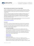
8 AOS DOES NOT ASSUME ANY LIABILITY ARISING. OUT OF SUCH APPLICATIONS OR USES OF ITS PRODUCTS. AOS RESERVES THE RIGHT TO IMPROVE Product DESIGN, FUNCTIONS AND RELIABILITY WITHOUT NOTICE. : March 2018 Page 2 of 6. AOD409/AOI409. TYPICAL ELECTRICAL AND THERMAL CHARACTERISTICS. 30 30. -10V VDS=-5V. -4V. 25 25. -5V. 20 20. -6V. -ID (A). -ID(A). 15 15. 10 10 125 C. 5 5 25 C. VGS=-3V. 0 0. 0 1 2 3 4 5 1 2 3 4 5. -VDS (Volts) -VGS(Volts). Figure 1: On-Region Characteristics (Note E) Figure 2: Transfer Characteristics (Note E). 60 2. Normalized On-Resistance 50 VGS=-10V.
9 VGS= ID=-20A. RDS(ON) (mW). 40. 30. VGS=-10V VGS= ID=-20A. 20 1. 10 0 5 10 15 20 25 0 25 50 75 100 125 150 175. -ID (A) Temperature ( C). Figure 3: On-Resistance vs. Drain Current and Gate Figure 4: On-Resistance vs. Junction Temperature Voltage (Note E) (Note E). 80 +01. ID=-20A. +00. 60 125 C RDS(ON) (mW). -IS (A). 125 C. 40 25 C. 25 C. 20 2 4 6 8 10 -VGS (Volts) -VSD (Volts). Figure 5: On-Resistance vs. Gate-Source Voltage Figure 6: Body-Diode Characteristics (Note E). (Note E). : March 2018 Page 3 of 6. AOD409/AOI409. TYPICAL ELECTRICAL AND THERMAL CHARACTERISTICS.
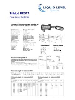
10 10 4500. VDS=-30V. ID=-20A 4000. 8 3500. Ciss Capacitance (pF). 3000. -VGS (Volts). 6. 2500. 2000. 4. 1500. 2 1000. Coss 500. Crss 0 0. 0 10 20 30 40 50 60 0 5 10 15 20 25 30. Qg (nC) -VDS (Volts). Figure 7: Gate-Charge Characteristics Figure 8: Capacitance Characteristics 500. TJ(Max)=175 C. TC=25 C. 10ms 400. 10ms RDS(ON). Power (W). 300. -ID (Amps). 100ms limited 1ms 10ms 200. DC. TJ(Max)=175 C 100. TC=25 C. 0. 1 10 100 1 10 100. -VDS (Volts). Pulse Width (s). VGS> or equal to Figure 10: Single Pulse Power Rating Junction-to- Figure 9: Maximum Forward Biased Case (Note F).