Transcription of General EJA510E and EJA530E Specifications …
1 GeneralSpecifications<<Contents>> <<Index>> EJA510E and EJA530 EAbsolute and gauge pressure TransmitterYokogawa Electric Corporation2-9-32, Nakacho, Musashino-shi, Tokyo, 180-8750 JapanTel.: 81-422-52-5690 Fax.: 81-422-52-2018GS 01C31F01-01 ENGS 01C31F01-01EN Copyright June 201213th Edition July 2016 The high performance absolute and gauge pressure transmitter EJA510E and EJA530E feature single crystal silicon resonant sensor and are suitable to measure liquid, gas, or steam pressure . EJA510E and EJA530E output a 4 to 20 mA DC signal corresponding to the measured pressure . It also features quick response, remote setup and monitoring via BRAIN or HART communications and self-diagnostics. FOUNDATION Fieldbus, PROFIBUS PA and 1 to 5 V DC with HART (Low Power) protocol types are also EJA-E series models in their standard configuration, with the exception of the Fieldbus, PROFIBUS and Low Power types, are certified as complying with SIL 2 for safety requirement.
2 STANDARD SPECIFICATIONSR efer to GS 01C31T02-01EN for Fieldbus communication type and GS 01C31T04-01EN for PROFIBUS PA communication type for the items marked with . SPAN AND RANGE LIMITS (For EJA510E , values are in absolute and lower range limits are 0.)MeasurementSpan/RangeMPapsi (/D1)bar(/D3)kg/cm2(/D4)ASpan10 to 200 to to to 2 Range 100 to 200 kPa to 29 1 to 2 1 to to to 2901 to 201 to 20 Range to 2 to 290 1 to 20 1 to to to 14505 to 1005 to 100 Range to 10 to 1450 1 to 100 1 to 100 DSpan *5 to 50720 to 720050 to 50050 to 500 Range * to 50 to 7200 1 to 500 1 to 500*: Maximum value shall be 70 MPa, 10150 psi, 700 bar or 700 kgf/cm2 respectively when /HG is specified. PERFORMANCE SPECIFICATIONSZero-based calibrated span, linear output, wetted parts material code S and silicone oil, unless otherwise Fieldbus and PROFIBUS PA communication types, use calibrated range instead of span in the following ConformanceEJA-E series ensures specification conformance to at least 3.
3 Reference Accuracy of Calibrated Span(includes the effects of terminal-based linearity, hysteresis, and repeatability)Measurement spanReference AccuracySpan XSpan<XA of Span ( URL/ span)% of SpanBCD ( 50 MPa/ span)% of Span[When /HAC is specified]Measurement spanReference AccuracySpan XSpan<XA of Span ( URL/ span)% of SpanB ( + URL/ span) % of SpanCD ( 50 MPa/ span)% of SpanMeasurement spanABCDX20 kPa( psi) MPa(29 psi)1 MPa(145 psi)8 MPa(1160 psi)URL (Upper range limit)200 kPa(29 psi)2 MPa(290 psi)10 MPa(1450 psi)50 MPa(7200 psi)2 All Rights Reserved. Copyright 2012, Yokogawa Electric Corporation<<Contents>> <<Index>>GS 01C31F01-01 ENAmbient Temperature Effects per 28 C (50 F) Change ( of Span + of URL) for A, B and C capsule. ( of Span + of 50 MPa) for D (All normal operating condition) EJA530E : of URL for 7 yearsEJA510E: of URL for 7 yearsPower Supply Effects % per Volt (from to 32 V DC, 350 )Vibration EffectsAmplifier housing code 1 and 3:Less than of URL when tested per the requirements of IEC60770-1 field or pipeline with high vibration level (10-60 Hz, mm displacement/60-2000 Hz 3 g)Amplifier housing code 2:Less than of URL when tested per the requirements of IEC60770-1 field with General application or pipeline with low vibration level (10-60 Hz displacement /60-500 Hz 2g)Mounting Position EffectsRotation in diaphragm plane has no effect.
4 Tilting up to 90 degree will cause zero shift up to kPa ( inH2O) which can be corrected by the zero Time (All capsules) 90 msWhen software damping is set to zero and including dead time of 45 ms (nominal) FUNCTIONAL SPECIFICATIONSO utput For 4 to 20 mA HART / BRAIN (Output signal code D and J)Two wire 4 to 20 mA DC output with digital communications, linear or square root programmable. BRAIN or HART FSK protocol are superimposed on the 4 to 20 mA range: mA to mAOutput limits conforming to NAMUR NE43 can be pre-set by option code C2 or C3. For 1 to 5 V HART (Output signal code Q)Three or four wire low power 1 to 5 V DC output with HART, linear or square root programmable. HART protocol are superimposed on the 1 to 5 V DC range: V to V DCFailure Alarm (Output signal code D and J) For 4 to 20 mA HART / BRAIN (Output signal code D and J)Output status at CPU failure and hardware error;Up-scale: 110%, mA DC or more (standard)Down-scale: 5%, mA DC or less For 1 to 5 V HART (Output signal code Q)Analog output status at CPU failure and hardware error;Up-scale: 110%, V DC or more (standard) Down-scale: 5%, V DC or lessDamping Time Constant (1st order)Amplifier s damping time constant is adjustable from to s by software and added to response : For BRAIN protocol type, when the software damping is set to less than s, communication may occasionally be unavailble during the operation, especially while output changes dynamically.
5 The default setting of damping ensures stable Period pressure : 45 msZero Adjustment LimitsZero can be fully elevated or suppressed, within the lower and upper range limits of the Zero Adjustment External zero is continuously adjustable with incremental resolution of span. Re-range can be done locally using the digital indicator with rangesetting Indicator (LCD display, optional) 5-digit numerical display, 6-digit unit display and bar indicator is configurable to display one or up to three of the following variables periodically; pressure in %, scaled pressure , measured also Factory Settings. Local Parameter Setting (Output signal code D, J and Q)Parameter configuration by the external zero adjustment screw and push button (Integral indicator code E) offers easy and quick setup for parameters of Tag number, Unit, LRV, URV, Damping, Output mode (linear/square root), Display out 1, and Re-range by applying actual pressure (LRV/URV).
6 Burst pressure LimitsA, B and C capsule: 30 MPaD capsule: 132 MPaSelf DiagnosticsCPU failure, hardware failure, configuration error, process alarm for pressure or capsule process high/low alarm for pressure is also availableSignal Characterizer (Output signal code D, J and Q)User-configurable 10-segment signal characterizer for 4 to 20 mA CertificationEJA-E series transmitters except Fieldbus, PROFIBUS PA and 1-5V DC with HART(Low Power) communication types are certified in compliance with the following standards;IEC 61508: 2000; Part1 to Part 7 Functional Safety of Electrical/electronic/programmable electronic related systems; SIL 2 capability for single transmitter use, SIL 3 capability for dual transmitter use. NORMAL OPERATING CONDITION (Optional features or approval codes may affect limits.)
7 Ambient Temperature Limits 40 to 85 C ( 40 to 185 F) 30 to 80 C ( 22 to 176 F) with LCD displayProcess Temperature Limits 40 to 120 C ( 40 to 248 F)Oct. 24, 2014-003<<Contents>> <<Index>>All Rights Reserved. Copyright 2012, Yokogawa Electric CorporationGS 01C31F01-01 ENAmbient Humidity Limits0 to 100% RHMaximum Over PressurePressureCapsuleEJA510 EEJA530EA and BCD4 MPa abs (580 psia)20 MPa abs (2900 psia)60 MPa abs (8700 psia) *4 MPa (580 psig)20 MPa (2900 psig)60 MPa (8700 psig) **: 105 MPa (15200 psi) when /HG is pressure Limits (Silicone oil) Maximum pressure LimitsPressureCapsuleEJA510 EEJA530 EABCD200 kPa abs (29 psia)2 MPa abs (290 psia)10 MPa abs (1450 psia)50 MPa abs (7200 psia) *200 kPa (29 psig)2 MPa (290 psig)10 MPa (1450 psig)50 MPa (7200 psig) **: 70 MPa (10150 psi) when /HG is specified.
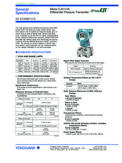
8 Minimum pressure LimitSee graph below-40(-40)0(32)40(104)80(176)120 (248) ( ) (1)1( )100(750)10(75) (20) ( ) ( )85 (185)(mmHg abs)WorkingpressurekPa absApplicable rangeProcess temperature C( F) 1-1. Working pressure and Process Temperature [For EJA510E ]Atmosphericpressure-40(-40)0(32) 40(104)80(176)120(248)1( ) ( )10( )(psia)100( )Process temperature C ( F)WorkingpressurekPa absApplicable 1-2. Working pressure and Process Temperature [For EJA530E ]Supply & Load Requirements (Output signal code D and J. Optional features or approval codes may affect electrical requirements.)With 24 V DC supply, up to a 550 load can beused. See graph below. ( )Power supply voltage E (V DC) and HARTR= 2. Relationship Between Power Supply Voltage and External Load Resistance (Output signal code D and J)Supply Voltage For 4 to 20 mA HART / BRAIN (Output signal code D and J) to 42 V DC for General use and flameproof to 32 V DC for lightning protector (option code A).
9 To 30 V DC for intrinsically safe, type n, non-incendive or non-sparking voltage limited at V DC for digital communications, BRAIN and HARTOct. 24, 2014-004 All Rights Reserved. Copyright 2012, Yokogawa Electric Corporation<<Contents>> <<Index>>GS 01C31F01-01EN For 1 to 5 V HART (Output signal code Q)Power supply :9 to 28 V DC for General use and flame proof type. Power Consumption : mA to 3 mA, 27 mW Load for 4 to 20 mA HART / BRAIN (Output signal code D and J)0 to 1290 for operation250 to 600 for digital communicationOutput Load for 1 to 5 V HART (Output signal code Q)1 M or greater (meter input impedance)Note that with three-wire connection, the cable length may affect the measurement accuracy of the output Requirements (Approval codes may affect electrical requirements.) BRAIN Communication DistanceUp to 2 km ( miles) when using CEV polyethylene-insulated PVC-sheathed cables.
10 Communication distance varies depending on type of cable used. Load F or less Load mH or less Input Impedance of communicating device10 k or more at Conformity StandardsEN 61326-1 Class A, Table2 (For use in industrial locations)EN 61326-2-3EN 61326-2-5 (for fieldbus)European pressure Equipment Directive 97/23/EC (until 18th July, 2016) 2014/68/EU (from 19th July, 2016)Sound Engineering Practice (for all capsules)With option code /PE3 (for D capsule)Category III, Module H, Type of Equipment: pressure Accessory-Vessel, Type of Fluid: Liquid and Gas, Group of Fluid: 1 and 2 Safety Requirement StandardsEN 61010-1, EN , Altitude of installation site: Max. 2,000 m above sea level Installation category: I (Anticipated transient overvoltage 330 V) Pollution degree: 2 Indoor/Outdoor use PHYSICAL SPECIFICATIONSW etted Parts Materials Diaphragm, Process ConnectorRefer to MODEL AND SUFFIX CODES.