Transcription of General FIO System Overview 6SHFL¿FDWLRQV …
1 GeneralSpecifications<<Contents>> <<Index>>FIO System Overview (for Vnet/IP)Yokogawa Electric Corporation2-9-32, Nakacho, Musashino-shi, Tokyo, 180-8750 JapanTel.: 81-422-52-5634 Fax.: 81-422-52-9802GS 33K50F10-50 EGS 33K50F10-50E Copyright Aug. 2011 (YK)9th Edition Feb. 1, 2015 (YK)n GENERALThe FIO (Fieldnetwork I/O) System is connected to the Field Control Unit (FCU) via an ESB, optical ESB, or ER Field Control Unit (AFV30 /AFV40 ) is connected to an ESB Bus Node Unit (ANB10 ) or an Optical ESB Bus Node Unit (ANB11 ). The Field Control Unit (AFV10 ) is connected to an ESB Bus Node Unit (ANB10 ) or an ER Bus Node Unit (ANR10 ).A node unit consists of a power supply module, a bus interface module, and input/output modules that are installed in a base unit. The power supply module, bus interface module, and input/output modules can be configured Unit for Optical ESB Bus Repeater Module (ANT10U) can be used to connect the optical ESB bus in a chain or star configuration.
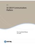
2 The following shows a System configuration Optical ESB Bus Node Unit ESB Bus Node Unit ESB Bus Node Unit I/O signal connection Dual-redundant ESB bus Dual-redundant ESB bus Dual-redundant Optical cable Dual-redundant Vnet/IP FCU: Field Control Unit TM1 READY FUSE RL1 CN1 (PSU-L) TM2 100-120V AC CN2 (PSU-R) Figure System Configuration2 All Rights Reserved. Copyright 2011, Yokogawa Electric Corporation<<Contents>> <<Index>>GS 33K50F10-50 EFeb. 1, 2015-00n COMMON SPECIFICATIONSl Installation EnvironmentItem Specification Ambient temperature Normal operating 0 to 50 C (AFV30 , AFV40 , ACB51, AFV10 ) 0 to 60 C (ANB10 , ANB11 , ANT10U, ANR10 , I/O Modules, Communication Modules, and Bus Interface Modules) (-20 to 70 C temperature option for ANB10 , ANB11 , ANT10U, ANR10 , I/O Modules, Communication Modules, and Bus Interface Modules) (*1) Transporting/storing -20 to 60 C (avoid direct sunlight.)
3 (-40 to 85 C temperature option for ANB10 , ANB11 , ANT10U, ANR10 , I/O Modules, Communication Modules, and Bus Interface Modules, avoid direct sunlight) Ambient humidity Normal operating 5 to 95 %RH (should have no condensation.) Transporting/storing 5 to 95 %RH (should have no condensation.) Ambient temperature change rate Normal operating Within 10 C/h Transporting/storing Within 20 C/h Power supply Voltage range 100 to 120 V AC 10 % 220 to 240 V AC 10 % 24 V DC 10 % Frequency 50/60 3 Hz Distortion factor 10 % or less Peak value 125 V or more (100 V System ) 274 V or more (220 V System ) Instantaneous power failure 20 ms or less (when receiving rated AC voltage) DC power supply ripple rate 1 % p-p or less Grounding 100 ohms or less, Independent grounding Dust mg/m3 or less Corrosive gas ANSI/ISA G2 (standard) (ANSI/ISA G3 option) Vibration Continuous vibration Displacement amplitude mm or less (1 to 14 Hz) Acceleration m/s2 or less (14 to 100 Hz) Earthquake Acceleration m/s2 or less Transport vibration Horizontal m/s2 or less, vertical m/s2 or less (packed state) Shock Transport shock Horizontal m/s2, vertical m/s2 (packed state)
4 Noise Electric field 3 V/m or less (26 MHz to GHz) 3 V/m or less ( to GHz) 1 V/m or less ( to GHz) Magnetic field 30 A/m or less (AC), 400 A/m or less (DC) Static electricity 4 kV or less (contact discharge), 8 kV or less (aerial discharge) Altitude 2000 m or less *1: When a ER Bus Node Unit is used under the temperature environment (-20 to 0 C), it requires 10 minutes to start up EB501 after turning on the power switch. When the following modules are installed in ESB Bus Node Unit, Optical ESB Bus Node Unit or ER Bus Node Unit, the ambient temperature should be 0 to 50 C. AAP149, AAP849, ADV157, ADV557, ADV161, ADV561, ADV859, ADV159, ADV559, ADV869, ADV169, ADV569, ALR111, ALF111, ALP111, ALP121 When AAI543- 6 , - F (fast response) is installed in ESB Bus Node Unit, Optical ESB Bus Node Unit or ER Bus Node Unit, the ambient temperature should be 0 to 60 <<Contents>> <<Index>>All Rights Reserved.
5 Copyright 2011, Yokogawa Electric CorporationGS 33K50F10-50 EAug. 1, 2013-00l ESB bus/Optical ESB busWhen using Field Control Unit (AFV30 /AFV40 )ApplicationAn ESB bus or an optical ESB bus is an input/output communication bus that connects the ESB bus node unit or optical ESB bus node unit to the intelligent part of the FCS. Communication SpecificationsConnectable Units: ESB Bus Node Unit (ANB10 ), Optical ESB Bus Node Unit (ANB11 ), and Unit for Optical ESB Bus Repeater Module (ANT10U)Number of Connectable Units: The number of ESB bus node units and optical ESB bus node units that can be connected to the ESB bus varies depending on the selected database. Units for Optical ESB Bus Repeater Module (ANT10U) are not included in the number of connectable Control UnitDatabaseTotal Number of ESB Bus and Optical ESB Bus Node Units Connected per FCU (*1)AFV30 (*2)AFV40 (*2) (*3)Control Function for Field Control Station (LFS1700)Max.
6 3 Control Function for Field Control Station (LFS1700) plus Node Expansion Package (LFS1750-V1)Max. 9 Control Function for Field Control Station (LFS1700) plus Node Expansion Package (LFS1750-V2) Max. 13*1: ESB Bus Node Unit (ANB10 ), Optical ESB Bus Node Unit (ANB11 )*2: To connect the ESB bus node unit and optical ESB bus node unit to the FCU (AFV30 /AFV40 ), install the ESB Bus Coupler Module (EC401 or EC402) in slots 7 and 8. EC401 can be connected a maximum of nine Node Units (ANB10 or ANB11 ). EC402 can be connected a maximum of nine Node Units (ANB10 or ANB11 ) on the upper and lower sides, respectively. The sum of the total number of Node Units (ANB10 or ANB11 ) per FCU should not exceed the specified number.*3: The maximum number of ESB bus node units, optical ESB bus node units, and units for optical ESB bus repeater module that can be installed in a single cabinet is 11 for AFV40.
7 Transmission Path SpecificationsNetwork Topology: Bus topologyTransmission Path Redundancy: AvailableTransmission Speed: 128 megabits per secondTransmission Cable: Dedicated cable (YCB301), an optical fiber cable (*1)Transmission Distance: Max. 10 m (*2), 50 km (when using the ANT411 Optical ESB Bus Repeater Module) (*3)*1: Optical Fiber Cable Specifications Connector Type: LC (compliant with IEC 61754-20) Recommended Cable: Quartz single-mode fiber (JIS C6835 SSMA IEC ) Number of Cores: 2*2: Max. 10 m for EC401 and max. 10 m on the upper and lower sides, respectively, for EC402. *3: The distance can be extended to a maximum of 50 km using the optical ESB bus repeater module. Chain and star connection configurations are available. l ESB busWhen using Field Control Unit (AFV10 )ApplicationA input/output communication bus used in a standard FCS for FIO. The ESB bus connects the processing unit of a FCS to local node SpecificationsField Control UnitDatabaseESB Bus Node Units Connected per FCU (*1)Total Number of ESB Bus Node Units and ER Bus Node Units Connected per FCU (*1)AFV10 (*2) Control Function for Field Control Unit (LFS1500)Max.
8 3 Max. 3 Control Function for Field Control Unit (LFS1500) plus Application Capacity Expansion Package (LFS1550)Max. 9 Max. 14*1: ESB Bus Node Units(ANB10 ), ER Bus Node Units(ANR10 )*2: If ESB Bus Node Units are used, install ESB Bus Coupler Module (EC401) in slot 7th and Path SpecificationsNetwork Topology: Bus topologyTransmission Path Redundancy: AvailableTransmission Speed: 128 megabits per secondTransmission Cable: Dedicated cable (YCB301)Transmission Distance: Max. 10 m4 All Rights Reserved. Copyright 2011, Yokogawa Electric Corporation<<Contents>> <<Index>>GS 33K50F10-50 ESep. 1, 2014-00l ER busWhen using Field Control Unit (AFV10 )ApplicationAn input/output communication bus used in a standard FCS for FIO. The ER bus connects local nodes or CompactField Control Unit for FIO to ER Bus Node SpecificationsField Control UnitDatabaseER Bus Node Units Connected per FCU (*1)Total Number of ESB Bus Node Units and ER Bus Node Units Connected per FCU (*1)AFV10 Control Function for Field Control Unit LFS1500 Max.
9 3 Max. 3 Control Function for Field Control Unit LFS1500 plus Application Capacity Expansion Package (LFS1550)Max. 14 (*2)Max. 14*1 ESB Bus Node Units(ANB10 ), ER Bus Node Units(ANR10 )*2: Up to 8 ER Bus Node Units per ER bus can be : Number of ER bus: Max. 4 per FCUT ransmission Path SpecificationsNetwork Topology: Bus topologyTransmission Path Redundancy: AvailableTransmission Speed: 10 megabits per secondTransmission Cable: Coaxial cable (YCB141, YCB311). Use YCB147/YCB149 Bus Adapter Unit to connect a YCB141 cable to a YCB311 cable. One grounding unit (YCB117) per segment (*1) should be used when connecting YCB311 Distance:YCB141: mWhen mixing YCB141 and YCB311:Length of YCB141 + (185/500) x Length of YCB311 185 Number of Bus Adapter Units: Max. 4 per segment (*1) General -purpose Ethernet Repeater:The total transmission distance is limited by the number of 4 - n L: total transmission distance (km) n: the number of the General -purpose Ethernet repeater (Max.)
10 4 repeaters)*1: If repeaters are used on ER bus, each part of the ER bus segregated by a repeater is referred to as a Regulatory ComplianceFor the detailed information of following standards, see System Overview (GS 33K01A10-50E) and GS on each Standards[CSA][CE Marking] (*1)[EAC Marking] (*1)EMC Conformity Standards[CE Marking] (*1)[EAC Marking] (*1)[RCM][KC Marking]Standards for Hazardous Location Equipment[CSA Non-Incendive][FM Non-Incendive] [Type n] (*2)[Type i (Intrinsic safety)] [FM Intrinsic safety] *1: ARS15M-1, ARS15M-2, ARS55M-1, ARS55M-2, ARS55M-3, ARS15B-6, and ADR541 do not comply with the Safety standard [CE Marking], [EAC Marking] and EMC conformity standard [CE Marking], [EAC Marking]. *2: ADR541 does not comply with the Standard for Hazardous location equipment [Type n].5<<Contents>> <<Index>>All Rights Reserved. Copyright 2011, Yokogawa Electric CorporationGS 33K50F10-50 EJune 1, 2012-00n STANDARD SPECIFICATIONSl Field Control Unit (for Vnet/IP and FIO)The following types of Field Control Unit (for Vnet/IP and FIO) are : Field Control Unit (for Vnet/IP and FIO, 19 Rack Mountable Type)AFV30D: Duplexed Field Control Unit (for Vnet/IP and FIO, 19 Rack Mountable Type)AFV40S: Field Control Unit (for Vnet/IP and FIO, with Cabinet)AFV40D: Duplexed Field Control Unit (for Vnet/IP and FIO, with Cabinet)For more detail, refer to Field Control Unit (for Vnet/IP) (GS 33K50E10-50E) and (GS 33K50E20-50E).