Transcription of GENERAL INSTALLATION, OPERATION, …
1 1 GENERAL installation , OPERATION, maintenance AND TROUBLESHOOTING manual FOR THREE SCREW AND CIG SERIES PUMPS WARNING This manual , and the pump specific Product Service manual , should be read thoroughly prior to pump installation , operation, maintenance or troubleshooting. CAUTION ATTENTION Page 2 of this manual has been added to emphasize the requirements of filling and venting the seal chamber prior to starting pump to prevent seal leakage and failures. manual No. SRM00046 Rev. 09 (15-0505) JULY 2015 Imo Pump 1710 Airport Road PO Box 5020 Monroe, NC USA Tel: + Email: Web: 2 Note: This page was added because of the prevalence of seal damage and leakage caused by not venting the seal chamber before putting a pump in service.
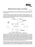
2 Seal Chamber Priming for pumps with seal vents: Fill mechanical seal chamber with liquid to insure seal does not start dry. This can be done by removing seal vent set-screw and pouring fluid into seal vent before opening pump inlet. Alternately, seal chamber can be vented in situations where inlet pressure is above atmospheric by opening inlet and discharge valves and then loosening seal vent plug to allow positive inlet pressure to push air out of seal chamber until oil flows from it. See figure below. Seal chamber priming for 3E model pumps with mechanical seals: For the Imo 3E Model pumps with mechanical seals, there is no seal vent port. The mechanical seal in these model pumps is located in the discharge chamber of the pump and is in the fluid flow path.
3 In these model pumps the complete pump must be filled and vented of any trapped air prior to starting the pump. Contact the factory if you have questions. See Figure 8 on page 12 and Figure 12 on page 18 of this manual for suction piping and pump filling methods. Filling or Venting Seal Cavity Using Seal Vent CAUTION - Failure to fill or vent seal chamber as described above may cause damage to seal running faces which may result in seal leakage. 3 READ THIS ENTIRE PAGE BEFORE PROCEEDING FOR SAFETY OF PERSONNEL AND TO PREVENT DAMAGE TO EQUIPMENT, FOLLOWING NOMENCLATURE HAS BEEN USED IN THIS manual : DANGER Failure to observe precautions noted in this box can result in severe bodily injury or loss of life.
4 WARNING Failure to observe precautions noted in this box can cause injury to personnel by accidental contact with equipment or liquids. Protection should be provided by the user to prevent accidental contact. CAUTION ATTENTION Failure to observe the precautions noted in this box can cause damage or failure of the equipment. Non compliance of safety instructions identified by following symbol could affect safety for persons: Safety instructions where electrical safety is involved are identified by: Safety instructions which shall be considered for reasons of safe operation of pump and/or protection of pump itself are marked by sign: ATTENTION ATTENTION If operation of this pump is critical to your business, we strongly recommend you keep a spare pump or major repair kit in stock at all times.
5 As a minimum, a minor repair kit (o-rings, gaskets, shaft seal and bearings) should be kept in stock so pump refurbishment after internal inspection can be accomplished. CONTENTS SAFETY AND TABLE OF CONTENTS .. 3 A - GENERAL .. 4 B - TRANSPORTATION AND STORAGE .. 4 C - DESCRIPTION OF THE PUMP .. 4 D - installation /ASSEMBLY .. 4 E - STARTUP, OPERATION AND SHUTDOWN .. 16 F - 20 G - FIELD AND FACTORY SERVICE .. 22 H - TROUBLESHOOTING .. 23 I UPACKAGING, INSPECTION & RE-PRESERVATION FOR PUMPS & MOTOR 24 - 25 J - UPACKAGING, INSPECTION & RE-PRESERVATION FOR PUMPS, PARTS & 26 4 APPLICATIONS manual FOR IMO PUMPS A. GENERAL Instructions found herein cover GENERAL installation , operation, maintenance and troubleshooting of subject equipment.
6 NOTE: Individual contracts may have specific provisions that vary from this manual . Should any questions arise which may not be answered by these instructions, refer to specific pump instruction manual provided with your order. For further detailed information and technical assistance to questions not answered by these manuals, please refer to Imo Pump, Technical/Customer Service Department, at (704) 289-6511. This manual cannot possibly cover every situation connected with installation , operation, maintenance and troubleshooting of equipment supplied. Every effort was made to prepare text of manual so that engineering and design data was transformed into easily understood wording. Imo Pump must assume personnel assigned to operate and maintain supplied equipment and apply instruction manual have sufficient technical knowledge and experience to use sound safety and operational practices which may not be otherwise covered by this manual .
7 In applications where equipment furnished by Imo Pump is to become part of a process or other machinery, these instructions should be thoroughly reviewed to determine proper fit of equipment into overall plant operational procedures. WARNING If installation , operation, and maintenance instructions are not correctly and strictly followed and observed, injury to personnel or serious damage to pump could result. Imo Pump cannot accept responsibility for unsatisfactory performance or damage resulting from failure to comply with instructions. B. TRANSPORTATION AND STORAGE Always protect the pump against taking in water and other contaminants. Store the pump in a clean, dry and relatively warm environment. Pumps are delivered with their internals oiled (unless specified otherwise by the customer order) and with protective covers in or over all openings.
8 These covers should remain in place during the mounting and alignment procedures. The covers must be removed just prior to attaching system piping to pump. If pumps are to be stored in other than a clean, warm, or dry environment, or if they are to be stored for more than six months, contact Imo for appropriate storage procedures. C. DESCRIPTION OF THE PUMP See specific pump instruction manual provided with your order. D. installation / ASSEMBLY WARNING On critical or dangerous equipment, provide safety and emergency systems to protect personnel and property from injury due to pump malfunction. If pumped liquids are flammable, toxic, corrosive, explosive or otherwise hazardous, provide for safety in the event of leakage or malfunction.
9 BEFORE working on equipment, make sure all power to equipment is disconnected and locked-out. 5 TOOLS Procedures described in this manual require common mechanics hand tools, dial indicators for alignment and suitable lifting devices such as slings, straps, spreader bars, etc. LIFTING OF PUMP AND PUMP/DRIVER ASSEMBLIES All pumps and pump/driver assemblies should be lifted with appropriate devices securely attached to whole unit. Ensure unit s center-of-gravity is located between lifting points. See Figure 1. This will avoid tipping of pump or pump/driver assembly. Spreader bars should be used as necessary to insure load is properly distributed and lifting straps do not damage equipment. Some pumps and pump/driver assemblies have designated lifting points that are shown on their outline drawings.
10 DANGER ATTENTION Lifting a vertical pump/driver using straps or hooks attached to the pump or pump-to-driver bracket may be dangerous since the center-of-gravity of the assembly may be higher than the points of attachment. Take precautions to prevent slippage of slings and hooks. Always use properly rated lifting devices. Max90 Min60 Max90 Min60 Max90 Figure 1 Lifting Pumps and Pump/Driver Assemblies installation OF PUMP ASSEMBLY To insure adequate flow of liquid to pump s inlet port, place pump near liquid source and preferably place pump centerline below liquid surface. Use short, straight inlet lines. A dry, clean, well-lit and well-ventilated site should be selected for installing the pump assembly. Sufficient open space should be provided around pump rotor and/or gear housing to permit routine visual inspection, on-site service and maintenance , and pump replacement.