Transcription of Maintenance and Service Instruction - Imo Pump
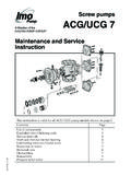
1 Screw pumps ACF/UCF. Maintenance and Service Instruction This Instruction is valid for all ACF/UCF pump models shown on page 2. Contents Page List of components 2. Exploded view/Ordering code/ Service intervals 3. Changing ball bearing/Inspection of rotors and shaft seal 4. List of tools/Sectional view 5. Shaft seal 6. Dismantling 6. Reassembly 8. Tuning valve 11. Pressure relief valve 11. ACF4 GB. List of components Valid for all ACF/UCF Generation 4 pumps with lead and sizes: 080, 090, 100 K4/N4; 110, 125L4/N4. with version codes: I R B O Also valid for pump options A101, A020, A084, A087. N V F P. E. Components included in Spare parts sets: Explanation: ACF = Pump Pos No Denomination Qty G011 G012 G050 G053 G054 G057 G070 Note with DIN flanges 113 Key 1 UCF = Pump 1010 Power rotor (CCW-rot.) 1 x (x) with ANSI. 1020 Power rotor (CW-rot.) 1 x x flanges 122 Ball bearing 1 x x x 123 Locking washer 1 x x x G011 = Rotor set 124 Bearing nut 1 x x x CCW-rot.
2 130 Support ring 1 x x x 132 Retaining ring 1 x x x G012 = Rotor set 201 Idler rotor (CCW-rot.) 2 x (x) CW-rot. 202 Idler rotor (CW-rot.) 2 x x G050 = Compl. 401 Pump body 1 shaft seal 424 Sleeve 1. 424A Gasket 1 x x x G053 = Minor kit 425 Screw 4 (G050+G057). 429 Spindle 1. 429A Pin 1 G054 = Major kit 430 Piston 1 1). G057 = Joint kit 432 Pin 1 1). 437 O-ring 1 x x x G070 = Valve 451 Screw 4-6 element 453 Screw 8. 455 Screw 8 Note: 462 Plug 1. 462A Sealing washer 1 x x x 1) Valid for sizes 463 Plug 1 100 - 125. 463A Sealing washer 1 x x x 480 Valve housing 1 5) 2) Delivered only 501 Front cover 1 as shaft seal 506 O-ring 1 x x x G050. 509A Rotating ring 1 x x x 2). 509C Rubber ring 1 x x x 3) Valid for pump 509D Washer 1 x x x xxxE, item no 509E Spring 1 x x x 601 - 658, 480. 511 Seat 1 x x x 2). 511A O-ring 1 x x x excluded 520 Bearing disc 1. 521 Screw 4 4) Number of 526 Grease nipple 1 shock valves: 526A Protective cap 1 size 080-090: 0.
3 537 Deaeration plug 1 100-110: 1, 537A Washer 1 125: 2. 551 Rear cover 1 3). 556 Gasket 1 x x x 5) Valid for pump 601 Top cover 1 x 5) xxxO/xxxP. 602 Gasket 2 x x x x 5). 605 O-ring 1 x x x x 5). 606 Bottom cover 1 x 5). 608 Valve spindle 1 x 5). 612 Regulating nut 1 x 5). 613 Pin 1 x 5). 6140 Valve piston 1 x 5). 615 Spring 1 x x 5). 621 Wheel 1 x 5). 622 Nut 1 x 5). 622A Key 1 x 5). 623 Valve plate 1 x 5). 636 Shock valve 0-2 x 4) 5). 655 Washer 1 x 5). 656 Sleeve 1 x 5). ACF4 GB. 657 Spring 1 x 5). 658 Distance sleeve 1 x 5). 2 Before commencing any work, read this Instruction carefully! Failure to comply with these instructions may ! cause damage and personal injury! For more information about the pumps identification code, technical data and performance we refer to the ACF Product description. Fore more information about the pumps installation, Start-up and trouble shooting we refer to the IMO.
4 Installation and Start-up Instruction for low pressure pumps. 455 606. Exploded view 602. 612. 613. 201 636 615 658. 113. 655. 480 608. 462 6140. 1010. 462 A 453. 622 A. 401. 537A 556 656. 537. 451 506 657. 122 526 A 501 605. 123 526 602. 124 601. 621. 520. 623. 521 622. 455. 463. 511 A 463 A 432 551. 511 429 A. 130 132 424. 425. 430. 113 429. 437. 424 A. 509 A Tu n ing Pa 509 E 1020 202 rts 509 C 509 D. Fig. 1. Ordering code Spare parts sets Pump size Recommended spare parts kits Pos No 080 090 100 110 125 Every shutdown for Service of a plant is costly. The G011 Rotor set N-lead 188661 171249 175638 time for repair should therefore be limited to a CCW K-lead 189665 189666 189667 minimum which can be accomplished by keeping a " L-lead spare pump. The changed pump can later be re- G012 Rotor set N-lead 105411 105429 105437 105445 105460 paired at a suitable place and can then be used as a CW K-lead 187518 187526 187534 spare pump.
5 " L-lead 105452 105478 For Maintenance the following spare parts kits are G050 Shaft seal xRxx 105486 105494 105502 105502 105502 recommended: " xVxx 175562 183467 175570 175570 175570 Kit Contents To be used for G057 Joint kit * xRxx 183335 183350 183376 183392 183418. G057 Gaskets, ballbearing, etc. Dismantling of the " xVxx 183343 183368 183384 183400 183426. pump G070 Valve G053 G057 + shaft seal G050 Normal scheduled element IxxO 066092 066092 066704 066704 067363. inspection " IxxP 189662 189662 189663 189663 189664. G054 G053+complete rotor set Repair after 615 Valve G012 (for CW rotation) damage or Spring xxxO 021451 021451 021766 021766 022061. + valve spring, item 615 greater wear " xxxP 021352 021352 021774 021774 022079. * not valid for A084 and A087. Wear in the pump will normally show as unnormal: Service intervals Vibration The intervals for inspection and replacement of wear Noise parts vary greatly with the properties of the pumped Loss of capacity liquid and can only be determined by experience.
6 Reduction in flow/pressure Except for the ball bearing, all internal parts of the Leakage ACF-pump are lubricated by the pumped liquid. We recommend planned inspection and overhaul at Pumping liquid which contain abrasive materials, or regular intervals, not exceeding 3 years. It is recom- ACF4 GB. liquid that is corrosive, will significantly reduce mended always to have the spares included in Service life and call for shorter Service intervals. minor spare part kit G053 available. 3. Use an appropriate type of grease, as per table and Changing ball bearing grease gun suitable for grease nipple (pos 473). according to DIN 71412 (ISO 6392). The ACF-pump is fitted with an external grease On vertical mounted units the greasing intervals are lubricated ball bearing. reduced to half. When delivered from IMO AB, the ball bearings are Installed in dusty or dirty premises or in a corrosive filled with grease of type B.
7 Environment it should be lubricated at more fre- Whenever the ball bearing is removed, it is recom- quent intervals. mended to exchange it for a new one. If using others than these recommended greases Fit the new ball bearing properly greased and re- check if it is possible to mix them with each other, grease it after one hour of running, while the pump is otherwise clean before using a new grease. operating. Lubrication intervals Recommended greases: Pump size Grease Temp Grease Speed, rpm Type A. amount max type 1750 1450 1150 950 BP Energrease LS3. gram C Lubricating intervals in working hours Esso Beacon 3. Mobil Mobilux 2. 70 A 10 000 10 000 10 000 10 000 Shell Alvania G3. 080 90 A 3 900 4 700 5 300 5 900 Texaco Multifak EP 2. and 15 90 B 7 900 9 500 10 000 10 000 Type B. 090 110 B 3 100 3 700 4 200 4 700 BP Energrease, HTG2. 130 B 1 200 1 500 1 600 1 800 Chevron Industrial 155 C 450 600 650 650 Grease Heavy Esso Unirex N3.
8 70 A 9 000 10 000 10 000 10 000. Mobil Mobiltemp, 100, 110 90 A 3 500 3 900 4 700 5 300. SHC 100. and 23 90 B 7 100 7 900 9 500 10 000 Shell Darina 2. 125 110 B 2 800 3 100 3 700 4 200 Texaco Hytex EP 2. 130 B 1 100 1 200 1 500 1 600 Type C. 155 C 300 450 600 600 Mobilith SHC 460. Inspection of rotors Inspection of shaft seal To reach the idler rotors in a quicker way than As the seal faces of a mechanical shaft seal are lubri- described in the dismantling section, loosen the rear cated by the fluid a certain leakage will always be cover (480) with valve. Screw out the idler rotors present. Ten drops per hour can be considered as backwards. acceptable. Internal clearances in the pump, which are vital for An external visual inspection of the pump is advis- its proper function, may have been affected by wear. able at least every two days to assure that the shaft Acceptable wear can be determined only by experi- seal is not leaking too much.
9 Excessively leaking shaft ence of the actual application. As a rule of thumb the seals should be changed without delay, as the leakage following max clearance values may apply: normally will grow worse and cause additional Between rotor and bores: mm damage. Follow the instructions in the dismantling/. Between rotor flanks: mm reassembly session. When working with a shaft seal, cleanliness is of For light duties (low pressure, medium viscosity) utmost importance. Avoid touching the seal faces. even bigger clearances may be acceptable but for If necessary, the seal faces should be cleaned imme- low pressure duties the limit will be diately prior to assembly, using a dust free cloth and lower. Also watch if there are major scratches on clean solvent. these parts. For lubrication of shaft seal read instructions in fig 23. If the pumps operating temperature ex- When handling liquids which may involve !
10 Ceeds 60 C let the pump cool off before any ! fire hazards appropriate precautions to Service , Maintenance or dismantling work avoid danger are to be taken. is commenced to avoid burn injury. In case of failure for a system with elevated All work carried out on the pump has to be ! pressure, fluid jets may cause injury and/or ! performed in such a manner that risks for damage. personal injury are observed! Oil leakage may make the floor slippery When handling liquids that may harm skin ! ACF4 GB. ! and cause personal injury. use gloves and/or protective clothing. 4 List of tools necessary for dismantling and reassembly d Threaded bar Washer UNC 5/8 70. GREASE. L Mounting sleeve ACF 4 IMO AB. Grease dimensions (mm). Pump D size d L. Slide Screw Hook Crow Plastic Puller Allen Pairs of Socket Mounting 080 46 150. key Pliers wrench sleeve Oil can calliper driver spanner bar mallet 090 51 150.