Transcription of General Model EJA120A Specifications Differential …
1 <<Contents>> <<Index>>. General Model EJA120A . Specifications Differential Pressure Transmitter GS 01C21B03-00E. The high performance draft range Differential pressure transmitter Model EJA120A outputs a 4 to 20 mA DC. signal corresponding to the measured Differential pressure. Model EJA120A also features remote setup and monitoring through communications with the BRAIN terminal and CENTUM CS or XL or HART 275 host. STANDARD Specifications . Refer to GS 01C22T02-00E for FOUNDATION Fieldbus communication type and GS 01C22T03-00E for PROFIBUS PA communication type marked with.
2 PERFORMANCE Specifications . Zero-based calibrated span, linear output, wetted parts material code S' and silicone oil. Reference Accuracy of Calibrated Span (including the effects of zero-based linearity, hyster- esis, and repeatability) FUNCTIONAL Specifications . Span & Range Limits % of Span % of Span when /HAC is specified Measurement kPa inH2O(/D1) mbar(/D3) mmH2O(/D4). Span and Range For spans below X, Span to 1 to 4 1 to 10 10 to 100. URL E. Range -1 to 1 -4 to 4 -10 to 10 -100 to 100. [ + ] % of Span X. [ + ] % of Span, when /HAC is URL is defined as the Upper Range Limit from the specified table.
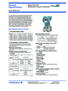
3 Where X equals: Zero Adjustment Limits Capsule X kPa {inH2O} Zero can be fully elevated or suppressed, within the E { } Lower and Upper Range Limits of the capsule. Square Root Output Accuracy External Zero Adjustment . The square root accuracy is a percent of flow span. External zero is continuously adjustable with %. incremental resolution of span. Span may be Output Accuracy adjusted locally using the digital indicator with range same as reference switch. 50 % or Greater accuracy Mounting Position Effect reference accuracy 50 Rotation in diaphragm plane has no effect.
4 Tilting up 50 % to Dropout point square root output (%) to 90 will cause zero shift up to kPa { inH2O}. which can be corrected by the zero adjustment. Output . Ambient Temperature Effects Two wire 4 to 20 mA DC output with digital communi- Total Effects per 28 C (50 F) Change cations, linear or square root programmable. BRAIN. [ % Span + % URL] or HART FSK protocol are superimposed on the 4 to Power Supply Effect 20 mA signal. % per Volt (from to 32 VDC, 350 ) Failure Alarm Output status at CPU failure and hardware error;. Up-scale: 110%, mA DC or more(standard).
5 Down-scale: -5%, mA DC or less , mA DC or less (Optional code /F1). Note: Applicable for Output signal code D and E. Yokogawa Electric Corporation GS 01C21B03-00E. 2-9-32 Nakacho, Musashino-shi, Tokyo, 180-8750 Japan Copyright June 1997. Phone: 81-422-52-5690 Fax : 81-422-52-2018 24th Edition April 2013. <<Contents>> <<Index>> 2. Damping Time Constant (1st order) Safety Requirement Standards The sum of the amplifier and capsule damping time EN61010-1. constant must be used for the overall time constant. Altitude of installation site: Max.
6 2,000 m above sea level Amp damping time constant is adjustable from to Installation category: I. 64 seconds. Pollution degree: 2. Indoor/Outdoor use Capsule (Silicone Oil) E. Communication Requirements . Time Constant (approx. sec) BRAIN. Ambient Temperature Limits Communication Distance (approval codes may affect limits) Up to 2 km ( miles) when using CEV polyethyl- -25 to 80 C (-13 to 176 F ) ene-insulated PVC-sheathed cables. Communication Process Temperature Limits distance varies depending on type of cable used. (approval codes may affect limits) Load Capacitance -25 to 80 C (-13 to 176 F) F or less (see note).
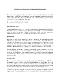
7 Ambient Humidity Limits Load Inductance 5 to 100 % RH @ 40 C (104 F) mH or less (see note). Working Pressure Limits Spacing from power line -50 to 50 kPa { to psi} 15 cm or more. Supply & Load Requirements Input Impedance of communicating device (Safety approvals can affect electrical requirements 10 k or more at kHz. (see graph below)). With 24 V DC supply, up to a 570 load can be used. Note : For General -use and Flameproof type. For Intrinsically safe type, please refer to OPTIONAL Specifications .'. PHYSICAL Specifications . 600. Wetted Parts Materials R=.
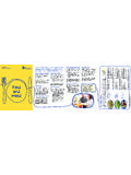
8 Diaphragm Digital Communication Hastelloy C-276. External load range Cover flange, Process connector resistance BRAIN and HART SCS14A. 250 Capsule Gasket PTFE Teflon R ( ). Vent and Drain Plug SUS316 or ASTM grade 316. Process Connector Gasket 42 PTFE Teflon Power supply voltage E (V DC) Fluorinated rubber for Optional code /N2 and /N3. Non-wetted Parts Materials Figure 1. Relationship Between Power Supply Voltage and External Load Resistance Bolting SCM435, SUS630, or SUH660. Supply Voltage Housing to 42 V DC for General use and flameproof type Low copper cast-aluminum alloy with polyurethane to 32 V DC for lightning protector (Optional paint (Munsell ).)
9 Code /A). Degrees of Protection to 30 V DC for intrinsically safe, Type n, IP67, NEMA4X. nonincendive, or non-sparking type Minimum voltage limited at V DC for digital Cover O-rings communications, BRAIN and HART Buna-N, fluoro-rubber (optional). Load (Output signal code D and E) Name plate and tag 0 to 1335 for operation SUS304 or SUS316 (option). 250 to 600 for digital communication Fill Fluid EMC Conformity Standards , Silicone, Fluorinated oil (option). EN61326-1 Class A, Table2 (For use in industrial Weight locations) kg ( lb) without integral indicator, mounting EN61326-2-3 bracket, and process connector.
10 European Pressure Equipment Directive 97/23/EC Connections Sound Engineering Practice Refer to the Model code to specify the process and electrical connection type. Process Connection of Cover Flange: DIN 19213 with 7/16 inch 20 unf female thread. All Rights Reserved. Copyright 1997, Yokogawa Electric Corporation GS 01C21B03-00E April 01, 2013-00. <<Contents>> <<Index>> 3. Model AND SUFFIX CODES. Model Suffix Codes Description EJA120A Differential pressure transmitter (for draft application). Output Signal -D .. 4 to 20 mA DC with digital communication (BRAIN protocol).