Transcription of General Model EJA120A Specifications Differential …
1 <<Contents>> <<Index>>. General Model EJA120A . Specifications Differential pressure transmitter GS 01C21B03-00E. The high performance draft range Differential pressure transmitter Model EJA120A outputs a 4 to 20 mA DC. signal corresponding to the measured Differential pressure . Model EJA120A also features remote setup and monitoring through communications with the BRAIN terminal and CENTUM CS or XL or HART 275 host. STANDARD Specifications . Refer to GS 01C22T02-00E for FOUNDATION Fieldbus communication type and GS 01C22T03-00E for PROFIBUS PA communication type marked with.
2 PERFORMANCE Specifications . Zero-based calibrated span, linear output, wetted parts material code S' and silicone oil. Reference Accuracy of Calibrated Span (including the effects of zero-based linearity, hyster- esis, and repeatability) FUNCTIONAL Specifications . Span & Range Limits % of Span % of Span when /HAC is specified Measurement kPa inH2O(/D1) mbar(/D3) mmH2O(/D4). Span and Range For spans below X, Span to 1 to 4 1 to 10 10 to 100. URL E. Range -1 to 1 -4 to 4 -10 to 10 -100 to 100. [ + ] % of Span X. [ + ] % of Span, when /HAC is URL is defined as the Upper Range Limit from the specified table.
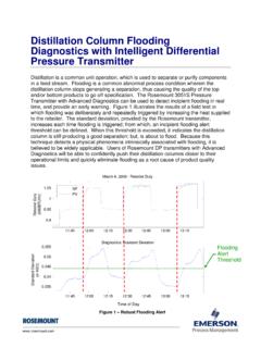
3 Where X equals: Zero Adjustment Limits Capsule X kPa {inH2O} Zero can be fully elevated or suppressed, within the E { } Lower and Upper Range Limits of the capsule. Square Root Output Accuracy External Zero Adjustment . The square root accuracy is a percent of flow span. External zero is continuously adjustable with %. incremental resolution of span. Span may be Output Accuracy adjusted locally using the digital indicator with range same as reference switch. 50 % or Greater accuracy Mounting Position Effect reference accuracy 50 Rotation in diaphragm plane has no effect.
4 Tilting up 50 % to Dropout point square root output (%) to 90 will cause zero shift up to kPa { inH2O}. which can be corrected by the zero adjustment. Output . Ambient Temperature Effects Two wire 4 to 20 mA DC output with digital communi- Total Effects per 28 C (50 F) Change cations, linear or square root programmable. BRAIN. [ % Span + % URL] or HART FSK protocol are superimposed on the 4 to Power Supply Effect 20 mA signal. % per Volt (from to 32 VDC, 350 ) Failure Alarm Output status at CPU failure and hardware error;. Up-scale: 110%, mA DC or more(standard).
5 Down-scale: -5%, mA DC or less , mA DC or less (Optional code /F1). Note: Applicable for Output signal code D and E. Yokogawa Electric Corporation GS 01C21B03-00E. 2-9-32 Nakacho, Musashino-shi, Tokyo, 180-8750 Japan Copyright June 1997. Phone: 81-422-52-5690 Fax : 81-422-52-2018 24th Edition April 2013. <<Contents>> <<Index>> 2. Damping Time Constant (1st order) Safety Requirement Standards The sum of the amplifier and capsule damping time EN61010-1. constant must be used for the overall time constant. Altitude of installation site: Max. 2,000 m above sea level Amp damping time constant is adjustable from to Installation category: I.
6 64 seconds. Pollution degree: 2. Indoor/Outdoor use Capsule (Silicone Oil) E. Communication Requirements . Time Constant (approx. sec) BRAIN. Ambient Temperature Limits Communication Distance (approval codes may affect limits) Up to 2 km ( miles) when using CEV polyethyl- -25 to 80 C (-13 to 176 F ) ene-insulated PVC-sheathed cables. Communication Process Temperature Limits distance varies depending on type of cable used. (approval codes may affect limits) Load Capacitance -25 to 80 C (-13 to 176 F) F or less (see note). Ambient Humidity Limits Load Inductance 5 to 100 % RH @ 40 C (104 F) mH or less (see note).
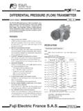
7 Working pressure Limits Spacing from power line -50 to 50 kPa { to psi} 15 cm or more. Supply & Load Requirements Input Impedance of communicating device (Safety approvals can affect electrical requirements 10 k or more at kHz. (see graph below)). With 24 V DC supply, up to a 570 load can be used. Note : For General -use and Flameproof type. For Intrinsically safe type, please refer to OPTIONAL Specifications .'. PHYSICAL Specifications . 600. Wetted Parts Materials R=. Diaphragm Digital Communication Hastelloy C-276. External load range Cover flange, Process connector resistance BRAIN and HART SCS14A.
8 250 Capsule Gasket PTFE Teflon R ( ). Vent and Drain Plug SUS316 or ASTM grade 316. Process Connector Gasket 42 PTFE Teflon Power supply voltage E (V DC) Fluorinated rubber for Optional code /N2 and /N3. Non-wetted Parts Materials Figure 1. Relationship Between Power Supply Voltage and External Load Resistance Bolting SCM435, SUS630, or SUH660. Supply Voltage Housing to 42 V DC for General use and flameproof type Low copper cast-aluminum alloy with polyurethane to 32 V DC for lightning protector (Optional paint (Munsell ). code /A). Degrees of Protection to 30 V DC for intrinsically safe, Type n, IP67, NEMA4X.
9 Nonincendive, or non-sparking type Minimum voltage limited at V DC for digital Cover O-rings communications, BRAIN and HART Buna-N, fluoro-rubber (optional). Load (Output signal code D and E) Name plate and tag 0 to 1335 for operation SUS304 or SUS316 (option). 250 to 600 for digital communication Fill Fluid EMC Conformity Standards , Silicone, Fluorinated oil (option). EN61326-1 Class A, Table2 (For use in industrial Weight locations) kg ( lb) without integral indicator, mounting EN61326-2-3 bracket, and process connector. European pressure Equipment Directive 97/23/EC Connections Sound Engineering Practice Refer to the Model code to specify the process and electrical connection type.
10 Process Connection of Cover Flange: DIN 19213 with 7/16 inch 20 unf female thread. All Rights Reserved. Copyright 1997, Yokogawa Electric Corporation GS 01C21B03-00E April 01, 2013-00. <<Contents>> <<Index>> 3. Model AND SUFFIX CODES. Model Suffix Codes Description EJA120A Differential pressure transmitter (for draft application). Output Signal -D .. 4 to 20 mA DC with digital communication (BRAIN protocol). -E .. 4 to 20 mA DC with digital communication (HART protocol, refer to GS 01C22T01-00E). -F .. Digital communication (FOUNDATION Fieldbus protocol, refer to GS 01C22T02-00E).