Transcription of General Model EJA440A Specifications Gauge Pressure ...
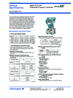
1 GeneralSpecifications<<Contents>> <<Index>>The high performance Gauge Pressure transmittermodel EJA440A can be used to measure liquid, gas,or steam Pressure . It outputs a 4 to 20 mA DC signalcorresponding to the measured Gauge EJA440A also features remote setup andmonitoring through communications with the BRAIN terminal and CENTUM CS or XL or HART 275host. STANDARD SPECIFICATIONSR efer to GS 01C22T02-00E for FOUNDATION Fieldbuscommunication type and GS 01C22T03-00E forPROFIBUS PA communication type marked with . PERFORMANCE SPECIFICATIONSZero-based calibrated span, linear output, wettedparts material code S and silicone Accuracy of Calibrated Span (including the effects of zero-based linearity,hysteresis, and repeatability) % of SpanFor spans below X, [ + ] % of SpanXSpanwhere X equals:8 MPa {1160 psi}Ambient Temperature Effects per 28 C (50 F) [ % Span + % URL]Stability % of URL per 60 monthsPower Supply Effects % per Volt (from to 32 V DC, 350 ) FUNCTIONAL SPECIFICATIONSSpan & Range LimitsCDMeasurementSpan and RangeSpanRangeSpanRangepsi (/D1)720 to 4500-15 to 4500720 to 7200-15 to 7200bar (/D3)50 to 320 kgf/cm2(/D4 )50 to 320-1 to 32050 to 500-1 to 500-1 to 32050 to 500-1 to 500 MPa5 to to 325 to to is defined as the Upper Range Limit from thetable Adjustment LimitsZero can be fully elevated or suppressed, within theLower and Upper Range Limits of the Zero Adjustment External zero is continuously adjustable with %incremental resolution of span.
2 Span may beadjusted locally using the digital indicator with Position EffectRotation in diaphragm plane has no effect. Tilting up to90 will cause zero shift up to kPa { inH2O}which can be corrected by the zero Two wire 4 to 20 mA DC output with digital communi-cations. BRAIN or HART FSK protocol are superim-posed on the 4 to 20 mA AlarmOutput status at CPU failure and hardware error;Up-scale:110%, mA DC or more(standard)Down-scale: -5%, mA DC or , mA DC or less (Optionalcode /F1)Note: Applicable for Output signal code D and EDamping Time Constant (1st order)The sum of the amplifier and capsule damping timeconstant must be used for the overall time damping time constant is adjustable from to64 (Silicone Oil) C DTime Constant (approx. sec) Temperature Limits(approval codes may affect limits)-40 to 85 C (-40 to 185 F)-30 to 80 C (-22 to 176 F) with LCD DisplayProcess Temperature Limits(approval codes may affect limits)-40 to 120 C (-40 to 248 F)Ambient Humidity Limits5 to 100 % RH @ 40 C (104 F) Model EJA440 AGauge Pressure TransmitterYokogawa Electric Corporation2-9-32 Nakacho, Musashino-shi, Tokyo,180-8750 JapanPhone: 81-422-52-5690 Fax: 81-422-52-2018GS 01C21E02-00 EGS 01C21E02-00E Copyright June 199726th Edition April 20132 All Rights Reserved.
3 Copyright 1997, Yokogawa Electric Corporation<<Contents>> <<Index>>GS 01C21E02-00E April 01, 2013-00 Maximum OverpressureCapsulePressureC48 MPa {6750 psig}D60 MPa {8500 psig}Working Pressure Limits (Silicone Oil)Maximum Pressure LimitCapsulePressureC32 MPa {4500 psig}D50 MPa {7200 psig}Minimum Pressure Limitsee graph belowAtmosphericpressure-40(-40)0(32)40( 104)80(176)120(248)1{ } { }10{ }{psi abs}100{ }Process temperature C ( F)WorkingpressurekPa absApplicable 1. Working Pressure and Process TemperatureSupply & Load Requirements (Safety approvals can affect electrical requirements(see graph below))With 24 V DC supply, up to a 570 load can beused. ( )Power supply voltage E (V DC) and HARTR= 2. Relationship Between Power Supply Voltageand External Load ResistanceSupply Voltage to 42 V DC for General use and flameproof to 32 V DC for lightning protector (Optionalcode /A) to 30 V DC for intrinsically safe, Type n,nonincendive, or non-sparking typeMinimum voltage limited at V DC for digitalcommunications, BRAIN and HARTLoad (Output signal code D and E)0 to 1335 for operation250 to 600 for digital communicationEMC Conformity Standards , EN61326-1 Class A, Table2 (For use in industriallocations)EN61326-2-3 European Pressure Equipment Directive 97/23/ECSound Engineering PracticeWith option code /PE3 Category III, Module H, Type of Equipment: PressureAccessory-Vessel, Type of Fluid: Liquid and Gas,Group of Fluid: 1 and 2 Safety Requirement StandardsEN61010-1 Altitude of installation site: Max.
4 2,000 m above sea level Installation category: I Pollution degree: 2 Indoor/Outdoor useCommunication Requirements BRAINC ommunication DistanceUp to 2 km ( miles) when using CEV polyethyl-ene-insulated PVC-sheathed cables. Communicationdistance varies depending on type of cable F or less (see note)Load mH or less (see note)Spacing from power line15 cm or Impedance of communicating device10 k or more at : For General -use and Flameproof Intrinsically safe type, please refer to OPTIONAL Specifications . 3<<Contents>> <<Index>>All Rights Reserved. Copyright 1997, Yokogawa Electric Corporation PHYSICAL SPECIFICATIONSW etted Parts MaterialsDiaphragmHastelloy C-276 Cover flangeSUSF316 Process connectorSCS14A (C Capsule)SUS316 (D Capsule)Capsule GasketTeflon-coated SUS316 LVent and Drain PlugSUS316 or ASTM grade 316 Process Connector O-ringFluorinated rubber (C Capsule with Process connec-tion code 3 and 4)Glass reinforced Teflon (C Capsule with Processconnection code 1 and 2 and D Capsule)Non-wetted Parts MaterialsBoltingSCM435, SUS630, or SUH660 HousingLow copper cast-aluminum alloy with polyurethanepaint (Munsell )Degrees of ProtectionIP67, NEMA4 XCover O-ringsBuna-N, fluoro-rubber (optional)Name plate and tagSUS304 or SUS316 (option)Fill FluidSilicone, Fluorinated oil (option)WeightC capsule: kg (15 lb) without integral indicator,mouting bracket, and process capsule.
5 Kg ( lb) without -tegral indicator,mouting bracket, and process to the Model code to specify the process andelectrical connection Connection of Cover Flange:DIN 19213 with 7/16 inch 20 unf female thread (CCapsule).GS 01C21E02-00E July 01, 2011-00< Settings When Shipped > Tag NumberOutput ModeDisplay ModeOperation ModeDamping TimeConstantCalibration RangeLower Range ValueCalibration RangeHigher Range ValueCalibration specified in order *1 Linear Linear Normal unless otherwise specified in order 2 sec. As specified in orderAs specified in orderSelected from mmH2O, mmAq, mmWG, mmHg, Pa, hPa, kPa, MPa, mbar, bar, gf/cm2, kgf/cm2, inH2O, inHg, ftH2O, or psi.(Only one unit can be specified)*1:Up to 16 alphanumeric characters for BRAIN and8 characters for HART including - and . will beentered in the amplifier memory. If specified Tagincludes other characters than above, it will notbe entered in the amplifier memory.< Related Instruments > Power Distributor: Refer to GS 01B04T01-02E orGS 01B04T02-02 EBRAIN TERMINAL: Refer to GS 01C00A11-00E< Reference >1.
6 Teflon; Trademark of DuPont de Nemours & Hastelloy; Trademark of Haynes International HART; Trademark of the HART FOUNDATION; Trademark of Fieldbus PROFIBUS; Registered trademark of ProfibusNutzerorganisation , Karlsruhe, Cross Reference TableSUS316 LSUS316 SUS304S25 CSCM435 SUS630 SCS14 AAISI 316 LAISI 316 AISI 304 AISI 1025 AISI 4137 ASTM630 ASTM Other company names and product names used inthis material are registered trademarks or trademarksof their respective owners.< Specification Conformance >The Model EJA440A maintains a specification con-formance to at least 3 .4 All Rights Reserved. Copyright 1997, Yokogawa Electric Corporation<<Contents>> <<Index>> Model AND SUFFIX .. -D .. -E .. -F ..-G .. C .. D .. S# .. 0 .. 1 .. 2 .. 3 .. 4 .. 5 .. A .. B .. C .. -2 .. -3 .. -6 .. -7 .. -8 .. -9 .. 0 .. 2 .. 3 .. 4 .. 5 .. 7 .. 8 .. 9 .. A.
7 C .. D .. D .. E .. N .. A .. B .. J .. C .. D .. K .. N .. ModelDescription EJA440 AOutput SignalMeasurement span(capsule)Wetted partsmaterial *8 Process connection *10 Bolts and nuts materialInstallationElectrical connectionIntegral indicatorMounting bracketOptional codesGauge Pressure transmitter4 to 20 mA DC with digital communication (BRAIN protocol)4 to 20 mA DC with digital communication (HART protocol, refer to GS 01C22T01-00E)Digital communication (FOUNDATION Fieldbus protocol, refer to GS 01C22T02-00E)Digital communication (PROFIBUS PA protocol, refer to GS 01C22T03-00E)5 to 32 MPa {50 to 320 kgf/cm2} {720 to 4500 psi} {50 to 320 bar}5 to 50 MPa {50 to 500 kgf/cm2} {720 to 7200 psi} {50 to 500 bar}[Body] [Capsule] [Vent plug]SUS316 *1 SUS316L *2 SUS316 *9without process connector (Rc 1/4 female on the cover flanges)with Rc 1/4 female process connectorwith Rc 1/2 female process connectorwith 1/4 NPT female process connector *6with 1/2 NPT female process connector *6without process connector (1/4 NPT female on the cover flanges)
8 [Maximum working Pressure ] [C Capsule] [D Capsule]SCM435 32 MPa {320 kgf/cm2} 50 MPa {500 kgf/cm2}SUS630 32 MPa {320 kgf/cm2} 50 MPa {500 kgf/cm2}SUH660 *5 32 MPa {320 kgf/cm2}Vertical impulse piping type, right side high Pressure , process connector upside*3 Vertical impulse piping type, right side high Pressure , process connector downside*3 Vertical impulse piping type, left side high Pressure , process connector upside*3 Vertical impulse piping type, left side high Pressure , process connector downside*3 Horizontal impulse piping type, right side high Pressure *4 Horizontal impulse piping type, left side high Pressure *4G1/2 female, one electrical connection 1/2 NPT female, two electrical connections without blind plug Pg female, two electrical connections without blind plug M20 female, two electrical connections without blind plugG1/2 female, two electrical connections and a blind plug1/2 NPT female, two electrical connections and a blind plug Pg female, two electrical connections and a blind plug M20 female.
9 Two electrical connections and a blind plugG1/2 female, two electrical connections and a SUS316 blind plug1/2 NPT female, two electrical connections and a SUS316 blind plugM20 female, two electrical connections and a SUS316 blind plugDigital indicatorDigital indicator with the range setting switch*7(None)SECC Carbon steel 2-inch pipe mounting (flat type)SUS304 2-inch pipe mounting (flat type)SUS316 2-inch pipe mounting (flat type)SECC Carbon steel 2-inch pipe mounting (L type)SUS304 2-inch pipe mounting (L type)SUS316 2-inch pipe mounting (L type)(None)/ Optional specificationSuffix Codes The marks indicate the most typical selection for each specification. Example: EJA440A -DCS5A-92NA / The # marks indicate the construction materials conform to NACE material recommendations per MR01-75. For the use ofSUS316 material, there may be certain limitations for Pressure and temperature. Please refer to NACE standards for details.
10 *1:Indicates material of cover flange and process connector;Capsule code C: cover flange; SUSF316, process connector; code D: cover flange; SUSF316, process connector; SUS316.*2:Diaphragm material is Hastelloy C-276 or ASTM N10276. Indicated is other capsule wetted parts material.*3:If necessary, specify Mounting bracket code C, D or K.*4:If necessary, specify Mounting bracket code A, B or J.*5:Not applicable for Capsule code D.*6:Lower limit of ambient and process temperature is 15C for Capsule code C.*7:Not applicable for Output signal code F and G.*8:Users must consider the characteristics of selected wetted parts material and the influence of process fluids. The use of inappropri-ate materials can result in the leakage of corrosive process fluids and cause injury to personnel and/or damage to plant facilities. Itis also possible that the diaphragm itself can be damaged and that material from the broken diaphragm and the fill fluid cancontaminate the user's process very careful with highly corrosive process fluids such as hydrochloric acid, sulfuric acid, hydrogen sulfide, sodium hypochlorite,and high-temperature steam (150 C [302 F] or above).