Transcription of General-Purpose Interface Compatible MR-J2M …
1 General-Purpose AC ServoMODELMR-J2M-P8 AMR-J2M- DUMR-J2M-BUSERVO AMPLIFIERINSTRUCTION MANUALG eneral- purpose Interface CompatibleJ2M SeriesEA - 1 Safety Instructions (Always read these instructions before using the equipment.)Do not attempt to install, operate, maintain or inspect the units until you have read through this InstructionManual, Installation Guide, Servo Motor Instruction Manual and appended documents carefully and can usethe equipment properly. Do not use the units until you have a full knowledge of the equipment, safetyinformation and this Instruction Manual, the safety instruction levels are classified into "WARNING" and "CAUTION". WARNINGI ndicates that incorrect handling may cause hazardous conditions,resulting in death or severe injury. CAUTIONI ndicates that incorrect handling may cause hazardous conditions,resulting in medium or slight injury to personnel or may cause that the CAUTION level may lead to a serious consequence according to conditions.
2 Please follow theinstructions of both levels because they are important to personnel must not be done and what must be done are indicated by the following diagrammatic symbols:: Indicates what must not be done. For example, "No Fire" is indicated by .: Indicates what must be done. For example, grounding is indicated by .In this Instruction Manual, instructions at a lower level than the above, instructions for other functions, and soon are classified into "POINT".After reading this Instruction Manual, always keep it accessible to the - 21. To prevent electric shock, note the following: WARNINGB efore wiring or inspection, switch power off and wait for more than 15 minutes. Then, confirm the voltageis safe with voltage tester. Otherwise, you may get an electric the base unit and servo motor to person who is involved in wiring and inspection should be fully competent to do the not attempt to wire for each unit and the servo motor until they are installed.
3 Otherwise, you can obtainthe electric the switches with dry hand to prevent an electric cables should not be damaged, stressed, loaded, or pinched. Otherwise, you may get an electric power-on or operation, do not open the front cover of the servo amplifier. You may get an not operate the servo amplifier with the front cover removed. High-voltage terminals and charging areaare exposed and you may get an electric for wiring or periodic inspection, do not remove the front cover even of the servo amplifier if thepower is off. The servo amplifier is charged and you may get an electric To prevent fire, note the following: CAUTIONDo not install the base unit, servo motor and regenerative brake resistor on or near a fire may each unit has become faulty, switch off the main base unit power side. Continuous flow of a largecurrent may cause a a regenerative brake resistor is used, use an alarm signal to switch main power off.
4 Otherwise, aregenerative brake transistor fault or the like may overheat the regenerative brake resistor, causing a To prevent injury, note the follow CAUTIONOnly the voltage specified in the Instruction Manual should be applied to each terminal. Otherwise, a burst,damage, etc. may the terminals correctly to prevent a burst, damage, that polarity (, ) is correct. Otherwise, a burst, damage, etc. may safety measures, provide covers, to prevent accidental contact of hands and parts (cables, etc.)with the servo amplifier heat sink, regenerative brake resistor, servo motor, they may be hotwhile power is on or for some time after power-off. Their temperatures may be high and you may get burntor a parts may operation, never touch the rotating parts of the servo motor. Doing so can cause - 34. Additional instructionsThe following instructions should also be fully noted.
5 Incorrect handling may cause a fault, injury, electricshock, etc.(1) Transportation and installation CAUTIONT ransport the products correctly according to their in excess of the specified number of products is not not carry the servo motor by the cables, shaft or not hold the front cover to transport each unit. Each unit may the each unit in a load-bearing place in accordance with the Instruction not climb or stand on servo equipment. Do not put heavy objects on servo amplifier controller and servo motor must be installed in the specified specified clearances between the base unit and control enclosure walls or other not install or operate the unit and servo motor which has been damaged or has any parts adequate protection to prevent screws and other conductive matter, oil and other combustiblematter from entering each unit and servo not drop or strike each unit or servo motor.
6 Isolate from all impact you keep or use it, please fulfill the following environmental unitServo motor[] 0 to 55 (non-freezing)0 to 40 (non-freezing)Duringoperation[] 32 to 131 (non-freezing)32 to 104 (non-freezing)[]20 to 65 (non-freezing)15 to 70 (non-freezing)AmbienttemperatureIn storage[]4 to 149 (non-freezing)5 to 158 (non-freezing)During operation 90%RH or less (non-condensing)80%RH or less (non-condensing)AmbienthumidityIn storage90%RH or less (non-condensing)AmbienceIndoors (no direct sunlight) Free from corrosive gas, flammable gas, oil mist, dust and dirtAltitudeMax. 1000m (3280 ft) above sea level[m/s2] or lessHC-KFS SeriesHC-MFS SeriesHC-UFS13 to 43XY : 49(Note) Vibration[ft/s2] or lessHC-KFS SeriesHC-MFS SeriesHC-UFS13 to 43XY : 161 Note. Except the servo motor with reduction attach the servo motor to the machine.
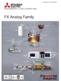
7 If attach insecurely, the servo motor may come off servo motor with reduction gear must be installed in the specified direction to prevent oil safety measures, provide covers, to prevent accidental access to the rotating parts of the servomotor during hit the servo motor or shaft, especially when coupling the servo motor to the machine. The encodermay become not subject the servo motor shaft to more than the permissible load. Otherwise, the shaft may the equipment has been stored for an extended period of time, consult - 4 (2) Wiring CAUTIONWire the equipment correctly and securely. Otherwise, the servo motor may not install a power capacitor, surge absorber or radio noise filter (FR-BIF option) between the servomotor and drive the output terminals (U, V, W) correctly. Otherwise, the servo motor will operate the servo motor power terminal (U, V, W) to the servo motor power input terminal (U, V, W)directly.
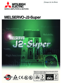
8 Do not let a magnetic contactor, etc. unitVWUVWS ervo MotorDo not connect AC power directly to the servo motor. Otherwise, a fault may surge absorbing diode installed on the DC output signal relay of the servo amplifier must be wired inthe specified direction. Otherwise, the forced stop and other protective circuits may not unitControl outputsignalVINSGVINSGRARAI nterface unitControl outputsignal(3) Test run adjustment CAUTIONB efore operation, check the parameter settings. Improper settings may cause some machines to performunexpected parameter settings must not be changed excessively. Operation will be - 5(4) Usage CAUTIONP rovide an forced stop circuit to ensure that operation can be stopped and power switched person who is involved in disassembly and repair should be fully competent to do the resetting an alarm, make sure that the run signal of the servo amplifier is off to prevent anaccident.
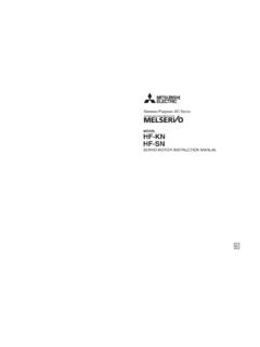
9 A sudden restart is made if an alarm is reset with the run signal not modify the a noise filter, etc. to minimize the influence of electromagnetic interference, which may be caused byelectronic equipment used near or breaking each unit may cause a toxic gas. Do not burn or break each the drive unit with the specified servo electromagnetic brake on the servo motor is designed to hold the motor shaft and should not be usedfor ordinary such reasons as service life and mechanical structure ( where a ballscrew and the servo motorare coupled via a timing belt), the electromagnetic brake may not hold the motor shaft. To ensure safety,install a stopper on the machine side. (5) Corrective actions CAUTIONWhen it is assumed that a hazardous condition may take place at the occur due to a power failure or aproduct fault, use a servo motor with electromagnetic brake or an external brake mechanism for thepurpose of the electromagnetic brake circuit so that it is activated not only by the Interface unit signals butalso by a forced stop (EMG_).
10 EMG_Contacts must be open whenservo-on (SON ) is off, when antrouble (ALM_ ) is present and when an electromagnetic brake interlock (MBR ).Circuit must be opened duringforced stop(EMG_ ).RA24 VDCE lectromagnetic brakeServo motorWhen any alarm has occurred, eliminate its cause, ensure safety, and deactivate the alarm beforerestarting power is restored after an instantaneous power failure, keep away from the machine because themachine may be restarted suddenly (design the machine so that it is secured against hazard if restarted).A - 6(6) Maintenance, inspection and parts replacement CAUTIONWith age, the electrolytic capacitor of the drive unit will deteriorate. To prevent a secondary accident dueto a fault, it is recommended to replace the electrolytic capacitor every 10 years when used in consult our sales representative.