Transcription of GI-2.0: Typical Wiring Diagrams - Rockwell …
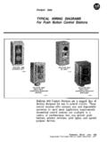
1 Wiring Diagrams ww introduction This booklet has been prepared as a guide to some of the useful ways Allen-Bradley s manual and magnetic across-the-line starters may be applied. It will also serve as a useful aid where simple Wiring systems are to be studied. When applying these Diagrams , it is well to remember that the features described in several Diagrams may be combined into one to produce another useful way of applying Allen-Bradley equipment. As you become familiar with the Diagrams , most such changes will prove simple. Exercises of this kind will be extremely beneficial to a student s better understanding of motor control Wiring dia- grams. It is important to note: A particular application must satisfy the needs of the user and comply with applicable codes, laws and standards before using any of the Typical circuits shown in this publication.
2 The symbols used in this booklet were adopted by Allen-Bradley for use in all its publications. They are in accordance with NEMA standards. The Allen-Bradley Company is very inter- ested in helping engineers, electricians and students to a better understanding of motor control equipment. It is our hope that this booklet furthers this purpose. contentsIntroduction .. Wiring Diagram Symbols ..Common and Important Terms.. , ..Bulletin 600 Manual Single Phase Starters .. 1 thru 4 7 Bulletin 609 Manual Starters .. 5 thru 13 Bulletin 509 Magnetic Full Voltage Using 3-Phase With START-STOP Transformer in Controls Control Operation (Backspin and Surge Protection)Sequence 505 Magnetic Reversing Button 520 Multi-Speed Motor Starters.
3 49 thru 51 PLATEPAGE14thru1718and1920thru242526and2 728thru3233and3435thru3738and3940thru444 546and4748 Wiring DIAGRAMSwnv24681112141518192023242627283 13234353 Key to Symbols Shown here are the symbols most often used in this book. Although the explanations accompanying the Diagrams describe the devices used, familiarity with the various symbols will lead to a quicker understanding of each circuit. The symbols, device designations, and abbreviations in this book are taken from the NEMA Standard Publication/No. ICS-1-1978. Wiring Diagram Symbols Symbol Symbol Device Fuse General Single Winding I Tapped Relay and Switch Coils Coils NE - Neon FL - Fluorescent --@I- P - Purple OP - Opalescent Permanent Magnet Economized Indicating Lights General Normally Closed ( ) 0 - Oranoe A - Amb& B - Blue #S#+i?
4 Main Auxiliary C - Clear G - Green R - Red W - White Y - Yellow Normally Open ( ) T -it- =E + Main Auxiliary 3 Phase Squirrel Cage Induction Single Phase Contacts Time Closing T Motors -=-I- T Time Opening Yellow 1 AC +IRed AC Solenoid Type Full Wave with Color Code Rectifier Contactors -_r::; Blk AC Yel Yel Manually Operated Wiring Diagrams c m w Devise Symbol Syfnbol Plugging Relays H-q+- ( Shown) Closing On Opening On Rising Press. Rising Press. T T T T Closing On Opening On Rising Temp. Rising Temp. Pressure and Temperature Thermal Overload Push Button Standard L LLLQ 0 0 NC NO rLl3 IiL 0 0 0 0 Mushroom Head Push Button Heavy Duty, Oiltight Switches Push Button and Jog Attachment Run&Jog 0 0 w Inst.
5 Aux. Contacts (when used) Timing (Pneumatic) (ON-DELAY) On Delay 3p 9 Standard Duty Selector Switch Jo Jo 2 Position 3 Position Heavy Duty Selector 2-Position 1 2 Letter Posltlon AL Sm. I 2 Bo 0 Ed A x B X F c R Anti-Plugging Heavy Duty Selector 3-Position 1 2 3 s$ 0 Fi%d swtwt Normally Open 0 % Normally Closed x2 Xl Potential Trans- former Polarity , Mark Switehea Current Q-9 cd6 Held Closed Held Open m c Wiring Diagrams w SOME COMMON and IMPORTANT TERMS In this booklet, and wherever motor control is discussed, there are several terms which are used repeatedly but whose meanings are often not completely understood by the reader. These terms represent things which are actually quite simple and everyone should become familiar with them as standard motor control jargon.
6 UNDERVOLTAGE RELEASE Also Called: Low-Voltage Release Two-Wire Control These terms mean that the starter will drop out when there is a voltage failure and will pick up again as soon as voltage returns. Reference to the diagram below will show how this occurs. The pilot device is unaffected by the loss of voltage and its contact remains closed, ready to carry current as soon as line voltage returns to normal. Two wres lead from the plot devrce to the starter. Undervoltage release and two-wwe control should brrng to mrnd an automatrc p/lot devrce such as a lrmrt swrtch or float switch whose functron IS openmg and closrng the control crrcurt by means of a smgle contact.
7 UNDERVOLTAGE PROTECTION Also Called: Low-Voltage Protection Three-Wire Control These terms mean that the starter will drop out when there is a voltage failure but will not pick up automat- ically when voltage returns. The control circuit is completed through the STOP button and also through a holding contact (2-3) on the starter. When the starter drops out, this contact opens, breaking the control circuit until the START button is pressed once again. L3 % t T3 Three Wires Three wjfes lead from the p/lot devtce to thestarter. Undervoltage protection and three-wrre control should brmg to mrnd a START-STOP push button stat/on whrch IS the most common means of provrdrng this type of control.
8 The main distinction between the above two types of control is that with undervoltage release the coil circuit is maintained through the pilot switch contact, and with undervoltage protection it is maintained through a stop contact on the push button station and also an auxiliary contact on the starter. The designations two-wire and three-wire are used only because they describe the simplest applications of the two types. Actually, in other systems, there might be more wires leading from pilot device to starter but the principle of two-wire or three-wire control would still be present. Wiring Diagrams vs LINE Diagrams Most of the Diagrams in this book are shown in two ways.
9 There is a Wiring diagram and adjacent to it a line diagram. Line Diagrams are included because their use is becoming more widespread and we believe it is advantageous to learn to use them. Wiring Diagrams or connection Diagrams include all of the devices in the system and show their physical relation to each other. All poles, terminals, coils, etc. are shown in their proper place on each device. These Diagrams are helpful in Wiring -up systems, because connections can be made exactly as they are shown on the diagram. In following the electrical sequence of any circuit, however, the Wiring diagram does not show the connections in a manner that can be easily followed.
10 For this reason a rearrangement of the circuit elements to form a line diagram is desirable. The line diagram (sometimes referred to as an elementary diagram or a schematic diagram) is a representation of the system showing it in the simplest way. No attempt is made to show the various devices in their actual relative positions. All control devices are shown between vertical lines which represent the source of control power, and circuits are shown connected as directly as possible from one of these lines to the other. All connections are made in such a way that the functioning of the various devices can be easily traced. Note: In this publication the line Diagrams show the control circuits only - power circuits are omitted for clarity, since they can be traced readily on the Wiring Diagrams (heavy lines).