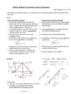
Transcription of Global Stiffness Matrix For Beams
1 Section 7: PRISMATIC BEAMSG lobal Stiffness Matrix For BeamsThe concept of an overall joint Stiffness Matrix will be explained in conjunction with the two span beam shown below. Here no loads are applied on the restrained structure and the six possible joint displacements are labeled. Keep in mind that the axial Stiffness is assumed to be large relative to flexural 7: PRISMATIC BEAMSAn overall Stiffness Matrix , [KJ ], can be generated that contains terms for all ibl j idi li l dipossible joint displacements, including those restrained at the supports. This Matrix involves application of unit displacements as shown in the figures to pgthe right and 7: PRISMATIC BEAMSEach column in the Stiffness Matrix below corresponds to the restraint reactions produced for each unit displacements application in the restrained structure.
2 Each row corresponds to an applied unit displacement There are six possible applied unit displacementsapplied unit displacement. There are six possible applied unit displacements. Note that the Matrix is square and symmetric. Expansion of the determinant of this Matrix would demonstrate that the Matrix is singular[K J] = that the Matrix is singular due to the fact that certain rows and columns are linear combinations of one 7: PRISMATIC BEAMSThe Matrix on the previous page was partitioned according to whether the displacements identified in the restrained structure, ,were free to displace in the original, unrestrained structureWith partitioning the Matrix can be considered to have four elements as follows[] DRKKK[] =RRRDJKKKS ection 7: PRISMATIC BEAMSThe upper left partition, [K],is a square, symmetric Matrix that corresponds to the unknown displacements.
3 The inverse of this Matrix is used in the expression{D} = [K]-1 {{AD} {ADL}}The lower left partition, {KRD }, is rectangular Matrix contains actions that correspond to the support restraints. This partition gives the reactions for the structure due to unit values of the unknown displacements. From the course Matrix Analysis of Structuresthe vector of support actions (moments or forces) would be obtained from{AR} = {ARL} + {KRD}{D}The upper right partition, {KDR }, is simply the transpose of {KRD }. The lower right hand partition, {KRR }, is square and symmetric. It contains actions corresponding to support restraints due to unit displacements in the restrained structure. The matrices {KDR }and {KRR} ill bdliid kdi lhiwill be used to analyze reactions associated known support displacements, zero or Stiffness Matrix [K]is only a small portion of [KJ].
4 This is a consequence of the fact that this particular structure is highly restrained to begin with. In large structures having many jidfhi[K]il if[K]joints and few supports, the Matrix [K]constitutes a large portion of [KJ].Section 7: PRISMATIC BEAMSIn Class ExampleSection 7: PRISMATIC BEAMSA rbitrary Numbering SystemsIn the previous section of notes the joint displacements were numbered in a convenient order, , translations proceeded rotations at each joint. Also, free displacements were numbered before constrained displacements. Consider the arbitrary numbering system below. If all matrices were generated conforming to the arbitrary numbering system below we could lose some if not all of the partition definitions developed in the last section ofwe could lose some, if not all, of the partition definitions developed in the last section of notes.
5 What is required of finite element software algorithms is the ability to take an arbitrary numbering system like the one above and transform it to the numbering system which ilidihdffd f hidihsegregates Matrix elements associated with degrees of freedom from those associated with support 7: PRISMATIC BEAMSThe [KJ ] Matrix for the arbitrary numbering system is the six by six Matrix shown below.[K J ] = Section 7: PRISMATIC BEAMSIn order for this [KJ ] Matrix to be useful the actual degrees of freedom and support constraints in the structure must be recognized. If the fourth and sixth rows are switched to the first and second rows while all others move downward we obtain the following Matrix :the first and second rows, while all others move downward, we obtain the following Matrix :Section 7: PRISMATIC BEAMSNext the fourth and sixth column are moved to the first and second column, while all other columns move to the right without changing order.
6 This rearrangement produces the [KJ] Matrix we had previously i ematrix we had previously, , Software algorithms must ghave the capability to track degrees of freedom and perform the necessary Matrix manipulation inmatrix manipulation in order to identify pertinent information.[K j ] = Section 7: PRISMATIC BEAMSA nalysis of Continuous Beams in GeneralContinuous Beams considered here are prismatic, rigidly connected to each beam segment p,gygand supported at various points along the beam . Joints are selected at points of support, at any free end, and changes in cross section ( , the beam is prismatic).A continuous beam havingmA continuous beam having mmembers and m+1joints is depicted in figure (a) to the restraints of two typesSupport restraints of two types may exist at any joint in a continuous beam . These are restraints against rotation and/or restraints against will only consider flexural deformations.
7 Torsion and axial di lidddisplacements are not considered. Thus only two displacements can occur at each 7: PRISMATIC BEAMSG iven the numbering system in figure (b) the translation at a particular joint is numbered prior to a rotation and it follows that the number of translations is equal to the number of joints minus one, while the rotation is twice the joint number. Thus at joint jthe joints minus one, while the rotation is twice the joint number. Thus at joint jthe translations and rotation are number 2j-1and is evident that the total numberIt is evident that the total number of possible joint displacements is twice the joints (or 2nj). If the total number of support restraints against translation and rotations is denoted nr, then the actual degrees of freedom arerrjnmnnn += =222 Here nis the number of degrees of 7: PRISMATIC BEAMSTo relate the end displacements of a particular member to the displacements of a joint, consider a typical member in figure (c) below.
8 The member end displacements are numberedj1j2k1andk3and correspond to end displacements 1 2 3 and 4 in figureThe new notation helps facilitate computer programming The four endnumbered j1, j2, k1and k3and correspond to end displacements 1, 2, 3 and 4 in figure (b).computer programming. The four end displacements correspond to the four joint displacements as follows:kkjj121121 = =kkjjkkjj2222121121==Since j and kare equal numerically to id(i1)hand (i+1), then:22222121121+==+= =ikijikijThis indexing system is necessary to construct the joint Stiffness Matrix [Sj ]Section 7: PRISMATIC BEAMSThe analysis of continuous Beams consists of establishing the Stiffness Matrix and the load Matrix The mostmatrix and the load Matrix . The most important Matrix generated is the overall joint Stiffness Matrix [SJ ]. The joint Stiffness Matrix consists of contributions from the beam Stiffness Matrix [SM ].
9 It is convenient to assess the contributions for one typical member iand repeat the process for members 1 through the next step involves expressing the iffffi ihih fistiffness coefficients shown in the figure to the left in terms of the various member stiffnesses that contribute to the joint t 7: PRISMATIC BEAMSThis next step requires that the member stiffnesses be obtained from the Matrix below:[k]For example the contribution to the joint Stiffness (Sj )j1,j1from member i-1is the Stiffness Sm33for that member. Similarly, the contribution to (Sj )j1,j1from member iis thtiffSfbithe Stiffness Sm11from member iSection 7: PRISMATIC BEAMSIn general the contribution of one member to a particular joint Stiffness will be denoted by appending the member subscript to the member Stiffness itself. From this discussion one can see that the joint Stiffness Matrix coefficients are generated by the followingone can see that the joint Stiffness Matrix coefficients are generated by the following expressions:()()()()()()()()iMiMjjJiMiMj jJSSSSSS211431,2111331,1+=+= ()()()( )iMjkJiMjkJSSSS411,2311,1==which represent the transfer of elements of the first column of the member Stiffness Matrix [k]to the appropriate location in the joint Stiffness Matrix [Sj][]pp pj[j]Section 7: PRISMATIC BEAMSE xpressions analogous to the previous expressions are easily obtained for a unit rotation about the zaxis at joint j:()()()()()()()()iMiMjjJiMiMjjJSSSSSS22 1442,2121342,1+=+= ()()()( )iMjkJiMjkJSSSS422,2322,1==Expressions analogous to a unit ydisplacement at joint kare.
10 ()()SS()()()( )()()()1113311231,2132,1++===iMiMkkJiMkj JiMkjJSSSSSSS()()()()()()121431,2111331, 1+++=iMiMkkJiMiMkkJSSSS ection 7: PRISMATIC BEAMSF inally the expressions for a unit zrotation at joint kare:()()()()()( )()()()242,2142,1+===iMkjJiMkjJSSSSSSS() ()()()()()122442,2112341,1+++=+=iMiMkkJi MiMkkJSSSSSSThe last 4 sets of equations show that the sixteen elements of the 4 x 4member Stiffness Matrix [k]ifor member I contribute to the sixteen of the Stiffness Matrix [SJ]coefficients in a very regular pattern. This pattern can be observed in the figure on the next 7: PRISMATIC BEAMSFor this structure the number of joints is seven, the number of possible joint pjdisplacements is fourteen, and the joint Stiffness Matrix [SJ]is dimensionally 14 x 14. The indexing scheme is shown down the left hand edge and across the top. The contributions of individual members are indicated in the hatched block each ofindicated in the hatched block.