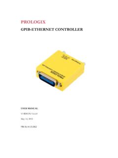
Transcription of GPIB-USB CONTROLLER - Prologix
1 Prologix GPIB-USB CONTROLLER USER MANUAL VERSION May 14, 2013 Prologix GPIB-USB CONTROLLER User Manual 5/14/2013 2 Table of Contents 1. Introduction .. 4 2. Installation .. 4 3. Firmware Upgrade .. 4 4. host Software .. 4 5. Configuration .. 5 6. Operating Modes .. 5 CONTROLLER Mode .. 5 Device Mode .. 6 7. Data Transmission .. 6 Binary Data Transmission .. 7 8. Commands .. 8 addr .. 8 auto .. 8 clr .. 9 eoi .. 9 eos .. 10 eot_enable .. 10 11 11 11 11 lon .. 11 mode .. 12 read .. 12 read_tmo_ms .. 13 rst .. 13 savecfg .. 13 spoll .. 14 srq .. 14 status .. 14 trg .. 15 ver .. 15 help .. 15 9. Specifications .. 15 Prologix GPIB-USB CONTROLLER User Manual 5/14/2013 3 Change Log May 14, 2013 Added ++llo command description.
2 April 18, 2011 Added ++lon command description. Sept 14, 2009 Added ++savecfg command descripion. Corrected maximum value of read_tmo_ms to 3000 ms. April 21, 2009 Added ++status command description. Updated ++addr, ++spoll and ++trg command descriptions to include secondary address. Added section on binary data transmission. Mar 1, 2008 Updated ++trg command description. Dec 22, 2007 Updated USB command terminator description and read_tmo_ms command description. Jul 9, 2007 Fixed typo in ++mode command description. Thanks Mike Schulz! Jul 7, 2007 Added change log. Renamed PERIPHERAL mode as DEVICE mode in line with other gpib literature. Jul 5, 2007 Initial version. Prologix GPIB-USB CONTROLLER User Manual 5/14/2013 4 1.
3 Introduction Prologix GPIB-USB CONTROLLER converts any computer with a USB port into a gpib CONTROLLER or Device. In CONTROLLER mode, Prologix GPIB-USB CONTROLLER can remotely control gpib enabled instruments such as Oscilloscopes, Logic Analyzers, and Spectrum Analyzers. In Device mode, Prologix GPIB-USB CONTROLLER converts the computer into a gpib peripheral for downloading data and screen plots from the instrument front panel. In both modes, Prologix GPIB-USB CONTROLLER interprets high level commands received from the host computer and performs the appropriate low-level gpib protocol handshaking. 2. Installation Prologix GPIB-USB CONTROLLER can be installed using these easy steps: 1. Download drivers for FT245R chip from FTDI website ( ) 2.
4 Connect Prologix GPIB-USB CONTROLLER to a computer using USB A-B cable 3. Install drivers according to instructions in 4. Plug CONTROLLER directly, or using a gpib cable, to the gpib connector on the instrument Two kinds of drivers are available: Virtual COM Port (VCP) driver and Direct (D2XX) driver. The VCP driver emulates a standard serial port on the host computer such that the Prologix GPIB-USB computer can be communicated with as a standard serial (RS-232) device. D2XX driver allows direct access to the CONTROLLER via a DLL interface . 3. Firmware Upgrade Prologix GPIB-USB CONTROLLER firmware is field upgradeable. Latest firmware and upgrade installations are available at 4. host Software A wide variety of host software may be used to communicate with Prologix GPIB-USB CONTROLLER : Terminal programs any terminal emulation program such as HyperTerminal, Tera Term Pro, or Minicom can be used to communicate with the CONTROLLER and instruments connected to it.
5 Prologix GPIB-USB CONTROLLER User Manual 5/14/2013 5 Custom applications any programming language or environment that provides access to serial ports (if using VCP driver) or allows interfacing to DLL (if using D2XX driver) may be used to develop custom applications. Graphical programming environments like National Instruments LabView and Agilent VEE may be used as well. EZGPIB an easy to use, programming environment developed by Ulrich Bangert for developing data acquisition applications. Web link to this tool can be found at Plotter emulators plotter emulation applications such as , PrintCapture and Plottergeist can be used to render screen plots downloaded using Prologix GPIB-USB CONTROLLER .
6 Details on how to configure these tools are available at 5. Configuration Prologix GPIB-USB CONTROLLER can be configured using any of the following methods: is an open source tool developed by John Miles for configuring the CONTROLLER . Web link to the tool can be found at Terminal program any terminal emulation program such as HyperTerminal, Tera Term Pro, or Minicom can be used to configure the CONTROLLER by manually entering appropriate commands (See Commands). Using the terminal program open the virtual COM port created by the USB driver. Serial port parameters such as baud rate, data bits, stop bits and flow control do not matter and may be set to any value. You may want to enable the Local Echo feature in the terminal program to view the commands being entered.
7 Please consult the FAQ at , or the program s user manual, for detailed configuration steps for various terminal programs. Prologix GPIB-USB CONTROLLER stores the latest configuration settings in non-volatile memory. These settings are not address specific. If you have multiple instruments on the gpib bus that require different configuration settings, you must change the settings before communicating with each instrument. 6. Operating Modes Prologix GPIB-USB CONTROLLER can operate in two modes CONTROLLER and DEVICE. You can switch between the two modes using ++mode command (see Commands). CONTROLLER Mode In CONTROLLER mode, the GPIB-USB CONTROLLER acts as the CONTROLLER -In-Charge (CIC) on the gpib bus.
8 When the CONTROLLER receives a command over the USB port terminated by the USB terminator CR (ASCII 13) or LF (ASCII 10) it addresses the Prologix GPIB-USB CONTROLLER User Manual 5/14/2013 6 gpib instrument at the currently specified address (See ++addr command) to listen, and passes along the received data. When Read-After-Write feature is enabled (See ++auto command) Prologix GPIB-USB CONTROLLER will addresses the instrument to talk after sending a command, in order to read its response. All data received from instruments over gpib is sent to host over USB. Read-After-Write feature simplifies communication with instruments. You send commands and read responses without consideration for low level gpib protocol details.
9 When Read-After-Write feature is not enabled Prologix GPIB-USB CONTROLLER does not automatically address the instrument to talk. You must use the ++read command to read data. CONTROLLER mode is used to remotely control instruments and to download screen plots by sending plot commands from a host computer. Device Mode In Device mode, Prologix GPIB-USB CONTROLLER acts as another peripheral on the gpib bus. In this mode, the CONTROLLER can act as a gpib TALKER or gpib LISTENER only. Since Prologix GPIB-USB CONTROLLER is not the CONTROLLER -In-Charge while in this mode, it expects to receive commands from a gpib CONTROLLER . When Device mode is enabled Prologix GPIB-USB CONTROLLER configures itself as a gpib Listener.
10 All data received by the CONTROLLER over the gpib port is passed along to the USB port without buffering. All data received from the host over USB is buffered until the gpib CONTROLLER addresses Prologix GPIB-USB CONTROLLER to talk, at which time the buffered data is passed along to the gpib port. The CONTROLLER can buffer only one command. A subsequent command received over USB will overwrite the previously buffered one, if the previous one has not yet been transmitted over gpib . Device mode is used to download screen plots from the instrument front panel for rendering using plotter emulation software. 7. Data Transmission In CONTROLLER and Device modes, characters received over USB port are aggregated in an internal buffer and interpreted when a USB termination character CR (ASCII 13) or LF (ASCII 10) is received.
