Transcription of MCP2515 Stand-Alone CAN Controller with SPI Interface …
1 2003-2019 Microchip Technology 1 MCP2515 Features Implements CAN at 1 Mb/s:- 0 to 8-byte length in the data field- Standard and extended data and remote frames Receive Buffers, Masks and Filters:- Two receive buffers with prioritized message storage- Six 29-bit filters- Two 29-bit masks Data Byte Filtering on the First Two Data Bytes (applies to standard data frames) Three Transmit Buffers with Prioritization and Abort Features High-Speed SPI Interface (10 MHz):- SPI modes 0,0 and 1,1 One-Shot mode Ensures Message Transmission is Attempted Only One Time Clock Out Pin with Programmable Prescaler:- Can be used as a clock source for other device(s) Start-of-Frame (SOF) Signal is Available for Monitoring the SOF Signal:- Can be used for time slot-based protocols and/or bus diagnostics to detect early bus degradation Interrupt Output Pin with Selectable Enables Buffer Full Output Pins Configurable as:- Interrupt output for each receive buffer- General purpose output Request-to-Send (RTS) Input Pins Individually Configurable as:- Control pins to request transmission for each transmit buffer- General purpose inputs Low-Power CMOS Technology:- Operates from 5 mA active current (typical)-1 A standby current (typical) (Sleep mode) Temperature Ranges Supported:- Industrial (I).
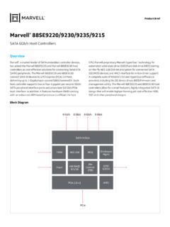
2 -40 C to +85 C- Extended (E): -40 C to +125 CDescriptionMicrochip Technology s MCP2515 is a stand -aloneController Area Network (CAN) Controller that imple-ments the CAN specification, Version It is capableof transmitting and receiving both standard andextended data and remote frames. The MCP2515 hastwo acceptance masks and six acceptance filters thatare used to filter out unwanted messages, therebyreducing the host MCU s overhead. The MCP2515interfaces with microcontrollers (MCUs) via an industrystandard Serial Peripheral Interface (SPI).Package Types 165 TXCANRXCANVDDRESETCSSOMCP251512341817161 5 SISCKINTRX0BF14131211RX1BF10 OSC2 OSC1 CLKOUT/SOFTX2 RTS5678 VSS9TX0 RTSTX1 RTSTXCANRXCANTX0 RTSOSC1 CLKOUT/SOFOSC2 CSVDDRESETSOSCKINTSIRX0 BFRX1 BFVSSTX1 RTSTX2 RTSNCNC18-Lead PDIP/SOIC20-Lead TSSOP2 NCTX2 RTSTX0 RTSSOSIOSC2 NCOSC1 GNDRX1 BFSCKRXCANTXCANVDDRESETTX1 RTSEP20119181734141312116789211015 CLKOUTCSINTRX0BF* Includes Exposed Thermal Pad (EP); see Table QFN* Stand-Alone CAN Controller with SPI InterfaceMCP2515DS20001801J-page 2 2003-2019 Microchip Technology : 2003-2019 Microchip Technology Inc.
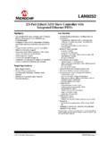
3 DS20001801J-page OVERVIEWThe MCP2515 is a Stand-Alone CAN Controller devel-oped to simplify applications that require interfacingwith a CAN bus. A simple block diagram of theMCP2515 is shown in Figure 1-1. The device consistsof three main blocks: CAN module, which includes the CANprotocol engine, masks, filters, transmit andreceive control logic and registers that are used toconfigure the device and its SPI protocol example system implementation using the device isshown in Figure ModuleThe CAN module handles all functions for receiving andtransmitting messages on the CAN bus. Messages aretransmitted by first loading the appropriate message buf-fer and control registers. Transmission is initiated byusing control register bits via the SPI Interface or byusing the transmit enable pins.
4 Status and errors can bechecked by reading the appropriate registers. Anymessage detected on the CAN bus is checked for errorsand then matched against the user-defined filters to seeif it should be moved into one of the two receive LogicThe control logic block controls the setup and operationof the MCP2515 by interfacing to the other blocks inorder to pass information and pins are provided to allow greater systemflexibility. There is one multipurpose interrupt pin (aswell as specific interrupt pins) for each of the receiveregisters that can be used to indicate a valid messagehas been received and loaded into one of the receivebuffers. Use of the specific interrupt pins is general purpose interrupt pin, as well as statusregisters (accessed via the SPI Interface ), can also beused to determine when a valid message has , there are three pins available to initiateimmediate transmission of a message that has beenloaded into one of the three transmit registers.
5 Use ofthese pins is optional, as initiating message transmis-sions can also be accomplished by utilizing controlregisters accessed via the SPI Protocol BlockThe MCU interfaces to the device via the SPI to, and reading from, all registers isaccomplished using standard SPI read and writecommands, in addition to specialized SPI 1-1:BLOCK DIAGRAM SPII nterfaceLogicSPIBusINTCSSCKSISOCANP rotocolEngineRXCANTXCANC ontrol LogicRX0 BFRX1 BFTX0 RTSTX1 RTSTX2 RTSTX and RX BuffersMasks and FiltersCAN ModuleRESETT imingGenerationOSC1 OSC2 CLKOUTC ontrolandInterruptRegistersMCP2515DS2000 1801J-page 4 2003-2019 Microchip Technology 1-2:EXAMPLE SYSTEM IMPLEMENTATION TABLE 1-1:PINOUT DESCRIPTION NamePDIP/SOIC Pin #TSSOPPin #QFN Pin #I/O/P TypeDescriptionAlternate Pin FunctionTXCAN1119 OTransmit output pin to CAN bus RXCAN2220 IReceive input pin from CAN bus CLKOUT331 OClock output pin with programmable prescalerStart-of-Frame signalTX0 RTS442 ITransmit buffer TXB0 Request-to-Send; 100 k internal pull-up to VDDG eneral purpose digital input,100 k internal pull-up to VDDTX1 RTS553 ITransmit buffer TXB1 Request-to-Send; 100 k internal pull-up to VDDG eneral purpose digital input,100 k internal pull-up to VDDTX2 RTS675 ITransmit buffer TXB2 Request-to-Send.
6 100 k internal pull-up to VDDG eneral purpose digital input,100 k internal pull-up to VDDOSC2786 OOscillator output OSC1897 IOscillator inputExternal clock inputVSS9108 PGround reference for logic and I/O pins RX1BF10119 OReceive buffer RXB1 interrupt pin or general purpose digital outputGeneral purpose digital outputRX0BF111210 OReceive buffer RXB0 interrupt pin or general purpose digital outputGeneral purpose digital outputINT121311 OInterrupt output pin SCK131412 IClock input pin for SPI Interface SI141614 IData input pin for SPI Interface SO151715 OData output pin for SPI Interface CS161816 IChip select input pin for SPI Interface RESET171917 IActive-low device Reset input VDD182018 PPositive supply for logic and I/O pins NC 6,154.
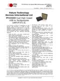
7 13 No internal connection EP 21 Exposed Thermal Pad, connect to VSS. Legend:I = Input; O = Output; P = PowerXCVRSPITXRXCANHCANLXCVRSPITXRXXCVRS PITXRXNodeControllerMCP2515 NodeControllerMCP2515 NodeControllerMCP2515 2003-2019 Microchip Technology Inc. DS20001801J-page Buffers/Masks/FiltersThe MCP2515 has three transmit and two receivebuffers, two acceptance masks (one for each receivebuffer) and a total of six acceptance filters. Figure 1-3shows a block diagram of these buffers and theirconnection to the protocol 1-3:CAN BUFFERS AND PROTOCOL ENGINE BLOCK DIAGRAMA cceptance FilterRXF2 RXB1 IdentifierData FieldData FieldIdentifierAcceptance MaskRXM1 Acceptance FilterRXF3 Acceptance FilterRXF4 Acceptance FilterRXF5 MABA cceptance FilterRXF0 Acceptance FilterRXF1 RXB0 TXREQTXB2 ABTFMLOATXERRMESSAGEM essageQueueControlTXREQTXB0 ABTFMLOATXERRMESSAGEC omparatorReceiveErrorTransmitErrorProtoc olRECTECErrPasBusOffFiniteStateMachineCo unterCounterShift[14:0]{Transmit[5:0], Receive[8.]}
8 0]}TransmitLogicTXRXC onfigurationRegistersClockGeneratorPROTO COLENGINEBUFFERSTXREQTXB1 ABTFMLOATXERRMESSAGEA cceptance MaskRXM0 AcceptAcceptSOFBitTimingLogicReceive[7:0 ]Transmit]7:0]Transmit Byte SequencerCRC[14:0]MCP2515DS20001801J-pag e 6 2003-2019 Microchip Technology Protocol EngineThe CAN protocol engine combines several functionalblocks, shown in Figure 1-4 and described FINITE STATE MACHINEThe heart of the engine is the Finite State Machine(FSM). The FSM is a sequencer that controls thesequential data stream between the TX/RX Shiftregister, the CRC register and the bus line. The FSMalso controls the Error Management Logic (EML) andthe parallel data stream between the TX/RX Shiftregisters and the buffers.
9 The FSM ensures that theprocesses of reception, arbitration, transmission anderror signaling are performed according to the CANprotocol. The automatic retransmission of messageson the bus line is also handled by the REDUNDANCY CHECKThe Cyclic Redundancy Check register generates theCyclic Redundancy Check (CRC) code, which istransmitted after either the Control Field (for messageswith 0 data bytes) or the Data Field and is used tocheck the CRC field of incoming messages. MANAGEMENT LOGICThe Error Management Logic (EML) is responsible forthe Fault confinement of the CAN device. Its two count-ers, the Receive Error Counter (REC) and the TransmitError Counter (TEC), are incremented and decrementedby commands from the bit stream processor.
10 Based onthe values of the error counters, the CAN Controller is setinto the states: error-active, error-passive or TIMING LOGICThe Bit Timing Logic (BTL) monitors the bus line inputand handles the bus related bit timing according to theCAN protocol. The BTL synchronizes on a recessive-to-dominant bus transition at the Start-of-Frame (hardsynchronization) and on any further recessive-to-dominant bus line transition if the CAN Controller itselfdoes not transmit a dominant bit (resynchronization).The BTL also provides programmable Time Segmentsto compensate for the propagation delay time, phaseshifts and to define the position of the sample pointwithin the bit time. The programming of the BTLdepends on the baud rate and external physical 1-4:CAN PROTOCOL ENGINE BLOCK DIAGRAMBit Timing LogicCRC[14:0]ComparatorReceive[7:0]Tran smit[7:0]Sample[2:0]MajorityDecisionStuf fReg[5:0]ComparatorTransmit LogicReceiveError CounterTransmitError CounterProtocolFSMRXSAMBusMonRec/Trm [7:0]TrmData[7:0]Shift[14:0](Transmit[5: 0], Receive[7:0])TXRECTECErrPasBusOffInterfa ce to Standard BufferSOF 2003-2019 Microchip Technology MESSAGE FRAMESThe MCP2515 supports standard data frames, extendeddata frames and remote frames (standard andextended), as defined in the CAN specification.