Transcription of GS110TP Hardware Installation Guide - Netgear
1 202-10596-01 March , East Plumeria DriveSan Jose, California 95134 USAGS110TP Hardware Installation , March 2010 2010 by Netgear , Inc. All rights , the Netgear logo, and Auto Uplink are trademarks or registered trademarks of Netgear , Inc. Microsoft, Windows, and Windows NT are registered trademarks of Microsoft Corporation. Other brand and product names are registered trademarks or trademarks of their respective holders. Portions of this document are copyright Intoto, of ConditionsIn the interest of improving internal design, operational function, and/or reliability, Netgear reserves the right to make changes to the products described in this document without does not assume any liability that may occur due to the use or application of the product(s) or circuit layout(s) described of the Manufacturer/ImporterIt is hereby certified that the GS110TP Smart PoE Switch has been suppressed in accordance with the conditions set out in the BMPT-AmtsblVfg 243/1991 and Vfg 46/1992.
2 The operation of some equipment (for example, test transmitters) in accordance with the regulations may, however, be subject to certain restrictions. Please refer to the notes in the operating instructions. The Federal Office for Telecommunications Approvals has been notified of the placing of this equipment on the market and has been granted the right to test the series for compliance with the regulations. Product and Publication DetailsModel Number:GS110 TPPublication Date:March 2010 Product Family:Gigabit Advanced Smart SwitchProduct Name: GS110TP Smart PoE SwitchHome or Business Product:BusinessLanguage:EnglishPublicat ion Part Number:202-10596-01 Publication Version , March 2010 ContentsGS110TP Hardware Installation GuideAbout This ManualConventions, Formats, and Scope .. vHow to Print this Manual .. viRevision History .. viChapter 1 IntroductionOverview ..1-1 Features ..1-2 PoE Features ..1-3 green Features ..1-3 Package Contents.
3 1-4 Chapter 2 Physical DescriptionGS110TP Front and Back Panel Configuration ..2-1 LED Designations ..2-2 Port LEDs ..2-2 System LEDs ..2-3 Device Hardware Interfaces ..2-3RJ-45 Ports ..2-3 Reset Button ..2-4 Factory Defaults Button ..2-4 Chapter 3 ApplicationsDesktop Switching .. , March 2010 Chapter 4 InstallationStep 1: Preparing the Site ..4-1 Step 2: Installing the Switch ..4-2 Installing the Switch on a Flat Surface ..4-2 Wall Mounting the Switch ..4-2 Step 3: Checking the Installation ..4-3 Step 4: Connecting Devices to the Switch ..4-3 Step 5: Applying AC Power ..4-4 Step 6: Managing the Switch using a Web Browser or the PC Utility ..4-4 Appendix A TroubleshootingTroubleshooting Chart .. A-1 Additional Troubleshooting Suggestions .. A-2 Network Adapter Cards .. A-2 Configuration .. A-2 Switch Integrity .. A-2 Auto-Negotiation .. A-3 Appendix B Technical , March 2010 About This ManualThe Netgear ProSafeTM GS110TP Hardware Installation Guide describes how to install and power on the GS110TP Smart PoE Switch.
4 The information in this manual is intended for readers with intermediate computer and Internet , Formats, and ScopeThe conventions, formats, and scope of this manual are described in the following paragraphs: Typographical Conventions. This manual uses the following typographical conventions:ItalicEmphasis, books, CDs, file and server names, extensionsBoldUser input, IP addresses, GUI screen textFixedCommand prompt, CLI text, code italicURL links Formats. This manual uses the following formats to highlight special messages:Tip: This format is used to highlight a procedure that will save time or : Ignoring this type of note may result in a malfunction or damage to the : This format is used to highlight information of importance or special : This is a safety warning. Failure to take heed of this notice may result in personal injury or Hardware Installation GuideviAbout This , March 2010 Scope. This manual is written for the GS110TP Smart PoE Switch according to these specifications:Product VersionGS110TP Smart PoE SwitchManual Publication DateMarch 2010 Note: Product updates are available on the Netgear , Inc.
5 Website at to Print this ManualTo print this manual, use the Complete PDF Manual link at the top left of any page. Click the Complete PDF Manual link at the top left of any page in the manual. The PDF version of the complete manual opens in a browser window. Click the print icon in the upper left of the window. Tip: If your printer supports printing two pages on a single sheet of paper, you can save paper and printer ink by selecting this HistoryPart NumberVersion 2010 Initial , March 2010 Chapter 1 Introduction Congratulations on the purchase of your Netgear GS110TP Smart PoE Switch. The GS110TP Smart PoE Switch is a supplement to the Gigabit Advanced Smart Switch family. Available as a desktop or wall-mountable switch, the GS110TP Smart PoE Switch is not intended to be rack-mountable. The GS110TP is a PoE-supportable, low-port switch with two fiber uplinks chapter serves as an introduction to the GS110TP Smart PoE Switch and provides the following information: Overview Features Package ContentsOverviewThis Installation Guide is for the Netgear GS110TP Smart PoE Switch.
6 This product offers support for eight 10/100/1000 Mbps autosensing and two 1000M SFP Gigabit Ethernet switching ports. Using Gigabit ports, high-speed connections can be made to a server or network backbone. For example: Linking to high-speed servers Providing 10/100/1000 Mbps copper connectivityThe GS110TP Smart PoE Switch also provides the benefit of administrative management with a complete package of features for the observation, configuration, and control of the network. With a Web-based Graphical User Interface (GUI), the switch s many capabilities can be viewed and used in a simple and intuitive manner. The switch s management features include configuration for port and switch information, VLAN for traffic control, port trunking for increased bandwidth, and Class of Service (CoS) for traffic prioritization. These features provide better understanding and control of the network. Initial discovery of the switch on the network requires the Netgear Smart Control Center program, a utility that runs on a Hardware Installation , March 2010 The GS110TP Smart PoE Switch is a free-standing switch.
7 It is IEEE-compliant and offers low latency for high-speed networking. All ports can automatically negotiate to the highest speed. This capability makes the switch ideal for environments that have a mix of Ethernet, Fast Ethernet, or Gigabit Ethernet devices. In addition, all RJ-45 ports operate in half-duplex or full-duplex mode. The maximum segment length is 328 feet (100 meters) over Category 5 Unshielded Twisted-Pair (UTP) following list identifies the key features of the GS110TP Smart PoE Switch: Eight RJ-45 10/100/1000 Mbps autosensing Gigabit Ethernet switching ports. Two 1000M SFP Gigabit Ethernet switching ports. Full Netgear Smart Switch functionality. Full compatibility with IEEE standards : IEEE CSMA/CD IEEE (10 BASE-T) IEEE (100 BASE-TX) IEEE (Full-duplex flow control) IEEE (1000 BASE-T) IEEE (1000 BASE-x) IEEE (DTE power via MDI) Autosensing and auto-negotiating capabilities for all ports. Auto Uplink on all ports to make the right connection.
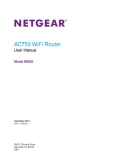
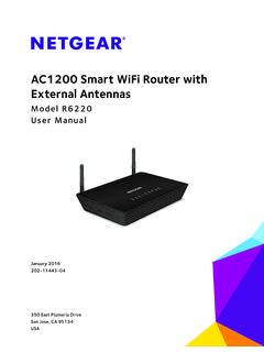
8 Automatic address learning function to build the packet-forwarding information table. The table contains up to 4K Media Access Control (MAC) addresses. Store-and-Forward transmission to remove bad packets from the network. Full-duplex IEEE pause frame flow control. Active flow control to minimize packet loss and frame drops. Half-duplex backpressure control. Per port LEDs, power Hardware Installation , March 2010 Standard Netgear 1xx series chassis. Netgear green product features. External 48 FeaturesThe GS110TP Smart PoE Switch supports IEEE PSE features: Ports 1 through 8 support IEEE , Alternative A (MDI-X). PoE is enabled by FeaturesThe GS110TP Smart PoE Switch supports the following power-saving features: The power consumption automatically adjusts based on the RJ-45 cable length. Each port is configured to power down automatically when the port link is Hardware Installation , March 2010 Package ContentsFigure 1-1 shows the package contents of the Netgear GS110TP Smart PoE 1-1 Verify that the package contains the following: Netgear GS110TP Smart PoE Switch Rubber footpads for tabletop Installation Wall mounting screws (2) External power adapter Installation Guide Smart Switch Resource CD with Netgear Smart Control Center and User s manualIf any item is missing or damaged, contact the place of purchase , March 2010 Chapter 2 Physical DescriptionThis chapter describes the Netgear GS110TP Smart PoE Switch Hardware features.
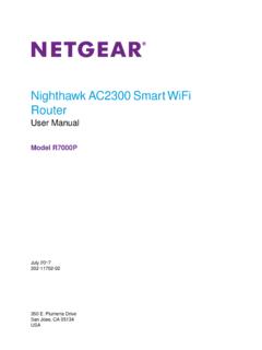
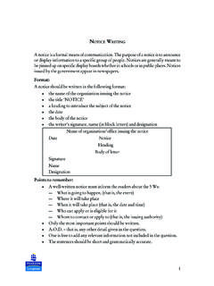
9 Topics include: GS110TP Front and Back Panel Configuration LED Designations Device Hardware InterfacesGS110TP Front and Back Panel ConfigurationThe GS110TP Smart PoE Switch has eight 10/100/1000 Mbps autosensing and two 1000 Mbps SFP Gigabit Ethernet switching ports. Each RJ-45 port is capable of sensing the line speed and negotiating the duplex mode with the link partner 2-1 illustrates the front panel of the Netgear GS110TP Smart PoE Switch:Power/Status LEDLink/Speed/ACT LEDs (left)10/100/1000 Mbps Ethernet PortsPoE Max LED1000M SFP PortsPoE Status LEDs (right)Figure 2-1 The front panel contains the following: Eight RJ-45 connectors for 10/100/1000 Mbps autosensing Gigabit Ethernet switching ports Two 1000M SFP Gigabit Ethernet switching ports Reset button to restart the device Recessed default reset button to restore the device back to the factory defaults Link, Speed, and Activity LEDs for each portGS110TP Hardware Installation Guide2-2 Physical , March 2010 Power and Status LED PoE Max LEDF igure 2-2 illustrates the Netgear GS110TP Smart PoE Switch back ConnectorFigure 2-2 The back panel contains the following.
10 A DC input for the supplied 48 external power adapterLED DesignationsPort LEDsThe following table describes the RJ-45 and SFP port LED designations. There are two LEDs for each RJ-45 port. Each SFP port has its own indication 2-1. Port LEDs LEDD esignationSpeed/Link/Activity (Left LED on each RJ-45 port) Off = No link is established on the port. Solid green = A valid 1000 Mbps link is established on the port. Flashing green = Packet transmission or reception is occurring on the port at 1000 Mbps. Solid Yellow = A valid 10/100 Mbps link is established on the port. Flashing Yellow = Packet transmission or reception is occurring on the port at 10/100 Hardware Installation GuidePhysical , March 2010 System LEDsThe following table describes the system LED 2-2. System LEDs LEDD esignationPower/Status LED Solid green = Power is supplied to the switch and the switch is operating normally. Solid Yellow = The switch is booting. Off = Power is MAX LED Off = There is at least 7W of PoE power available for another device.