Transcription of HD 101 R01-20 PDF
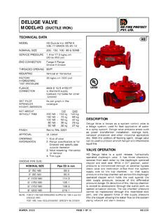
1 DELUGE VALVE. MODEL- A (CAST IRON) HD FIRE PROTECT. PVT. LTD. TECHNICAL DATA. MODEL A. NOMINAL SIZE 200, 150, 100, 80 & 50NB. MAXIMUM SERVICE 12 Bar (175 PSI). PRESSURE. THREADED OPENING BSPT. MOUNTING 90 pattern inlet to outlet vertical mounting FACTORY 25 (350 PSI). HYDROSTATIC. TEST PRESSURE. FLANGE ANSI B FF # 125. CONNECTION (Flange drilling matching to ANSI B # 150). and restriction orifice from the system supply side to TRIM Galvanized Steel with Brass the top chamber, so that supply pressure in the top valves chamber acts across the diaphragm operated clapper WET PILOT As per graph in the catalogue which holds the seat against the inlet supply pressure SPRINKLER because of differential pressure design. HEIGHT LIMITATION On detection of fire the top chamber is vented to NET WEIGHT 200NB - 214 Kg atmosphere through the outlet port via opened WITHOUT TRIM 150NB - 131 Kg actuation device(s). The top chamber pressure cannot 100NB - 77 Kg be replenished through the restricted inlet port, 80NB - 50 Kg thus it reaches less than half the supply pressure 50NB - 47 Kg instantaneously and the upward force of the supply pressure lifts the clapper allowing water to enter the FINISH Red RAL 3001 system piping network and alarm devices.
2 APPROVAL UL Listed TRIM DESCRIPTION. ORDERING Specify : INFORMATION 1) Size of valve a) BASIC TRIM. 2) Trim type - Dry Pilot The basic trim is required on deluge valve Wet Pilot regardless of the release system. It contain Electric Release those components which are required in all Test & Alarm types of installation, such as the main drain valve, priming connection, drip check valve, emergency release valve and pressure gauges. b) DRY PILOT TRIM (PNEUMATIC RELEASE). DESCRIPTION. Dry pilot operation uses a pilot line of closed Deluge Valve is known as a system control valve in a Sprinklers / QB detectors containing air under deluge system, used for fast application of water in a pressure, located in the area to be protected. spray system. Deluge valve protects areas such as It requires regulated dry air supply with main power transformer installation, storage tank, conveyor supply point through restricted orifice. protection and other industrial application etc.
3 With the addition of foaming agent deluge valve can be used The pilot line is connected directly to the top to protect aircraft hanger and inflammable liquid fire. of POSITIVE DRAIN ACTUATOR (PDA). The bottom of PDA is connected to the top chamber VALVE OPERATION of the deluge valve. Deluge valve is a quick release, hydraulically operated When the air pressure drops, due to release of diaphragm valve. It has three chambers, isolated from any of the release devices on detection of fire, each other by the diaphragm operated clapper and the diaphragm of PDA is lifted and allows the water seat seal. While in SET' position, water pressure is to drain. This reduces the water pressure in transmitted through an external bypass check valve the top chamber of the deluge valve and when JUNE, 2020 PAGE 1 OF 14 HD 101. HD FIRE PROTECT. PVT. LTD. the pressure in the top chamber reaches 50% of Note: Trim without Test and Alarm trim, without the supply pressure, the deluge valve opens.
4 Drain & drip valve can be supplied for which please contact marketing. The direct drain of PDA start when the top chamber pressure of deluge valve reaches approximately This positive drain will not permit RESETTING PROCEDURE FOR. the deluge valve to close unless the PDA is set (i) Close the upstream side stop valve provide manually. The recommended air supply pressure below the deluge valve. is as per TABLE-1. (ii) Open both the drain valves and close them when the flow of water has ceased. TABLE 1. LINE WATER AIR PRESSURE IN DETECTION (iii) Inspect and release if required, or close the PRESSURE LINE section of the detection system subjected to Fire condition . MAXIMUM MINIMUM MAXIMUM. (iv) In case of dry pilot detection system, open the 2 air supply valve to build-up air pressure as shown in TABLE-1. Open the priming valve fully and 4 press hold the knob of PDA till the water 6 pressure gauge indicate full service line 8 pressure, then release the PDA knob.
5 Open the upstream side of the stop valve provided below 10 the deluge valve. No water should flow into the 12 system, this can be checked by depressing the drip check valve knob. c) WET PILOT TRIM ( HYDRAULIC RELEASE ). CAUTION. Wet pilot operation uses a pilot line of closed sprinklers containing pressurised water, a. Do not close the priming valve, down stream and supplied through the upstream side of the deluge upstream stop valves , while the system is in valve, through a restricted orifice. All the release service. lines are connected to a common release line. b. The releasing device must be maintained in the Due to release of any one of the release devices, open position, when actuated, to prevent the water pressure in the top chamber of the the deluge valve from closure. deluge valve reaches 50% of the supply pressure, the deluge valve opens. c. While using a Deluge valve in the wet pilot system the height and the length of the wet CAUTION pilot detection line is to be limited as shown in the wet pilot sprinkler limitation graph.
6 While using a deluge valve in the wet pilot system the height and the length of the wet pilot detection line is d. Do not connect the Sprinkler Alarm outlet to be limited as given in the wet pilot sprinkler height drainline to close a common drain as it may limitation graph. create back pressure and Sprinkler Alarm may not fuction. d) ELECTRIC RELEASE TRIM. e. Deluge valve must have support to absorb To actuate a deluge valve electrically, a solenoid sudden opening or closing vibration shock valve is provided to drain the water from the top to the piping. chamber of the deluge valve. A pressure switch is provided to activate an electric alarm, to shut f. The responsibility of maintenance of the down the desired equipment or to give Tripped protection system and devices in proper indication to the panel. operating condition lies with the owner of the system. In addition to this two nos of pressure switchs can be used to monitor Low air g. Deluge Valve & its trim shall be maintained at pressure and Fire condition when used a minimum temperature of 4 C, Heat tracing in dry pilot air line.
7 Is not permitted. e) TEST AND ALARM TRIM WITH h. Deluge Valve must be used in pressurised SPRINKLER ALARM system This trim is supplied with the sprinkler alarm SYSTEM TESTING PROCEDURE. bell, which bells on actuation of the deluge valve. (i) Keep the upstream side of the stop valve A test valve is provided to test the normal partially open. Open the upstream side of the operation of the sprinkler alarm bell. JUNE, 2020 PAGE 2 OF 14 HD 101. HD FIRE PROTECT. PVT. LTD. drain valve, to maintain a minimum pressure of (iii) NORMAL CONDITION TEST. 3 cm on the upstream side of the deluge valve. To avoid water damage close the system (a) The system should be checked for normal side stop valve. This valve is to be kept in open condition at least once a month. position after the testing is completed. (b) Test the sprinkler alarm bell or electric alarm by (ii) Open the system side drain valve of the deluge turning the alarm test valve to the test position. valve. The alarm should sound.
8 This test should be carried out at least once in a week. (iii) Let any of the release devices to trip . This will result in a sudden drop of water pressure in (c) Depress the drip valve knob. Significant water the deluge valve top chamber resulting the accumulation indicates a possible seat leakage. deluge valve to open. The water flowing through (d) Conduct the water flow test as per the procedure the down stream side drain valve confirms that of system testing at least once in a month. the deluge valve has actuated, immediately close the upstream side stop valve . (iv) PERIODIC CHECK. (iv) Once testing is over reset the valve as Conduct the water flow test by actuating few of per procedure given under heading RESETTING the release devices provided in the system. PROCEDURE FOR THE DELUGE VALVE . Clean all strainer(s) and priming line restriction. This test is to be carried out at least once in six INSPECTION AND MAINTENANCE months. All the newly installed system piping network must ABNORMAL CONDITION.
9 Be flushed properly before placing the deluge valve in service. A qualified and trained person must (i) ALARM FAILS TO SOUND. commission the system. After few initial successful (a) Check for any obstruction in the alarm test line, tests an authorised person must be trained to Ensure that the sprinkler alarm is freely operating. perform inspection and testing of the system. It is recommended to have regular inspection and test run (b) If an electric alarm is provided, check the the system as per NFPA guidelines or in accordance electrical circuitry to the alarm. with the guideline laid down by the organisation having (ii) FALSE TRIPS. local jurisdiction. (a) Check for clogging in priming line, restriction (i) WARNING orifice check valve, priming valve & strainer. Inspection and testing is to be carried out only (b) Leakage in the release system. by authorised and trained personnel. DO NOT. TURN OFF the water supply or close any valve (c) The deluge air panel orifice clogged or low to make repair(s) or test the valve, without supply pressure.
10 Placing a roving fire patrol in the area protected (iii) LEAKAGE THROUGH THE DELUGE VALVE. by the system. Also inform the local security personnel and central alarm station, so that a (a) Damaged deluge valve seat or obstruction on false alarm is not signalled. It is recommended the seat face by foreign object. to carry out physical inspection of the system (b) Leakage in release system. at least twice in a week. (c) Partly clogged priming line, restriction check The inspection should verify that all the valve. control valves are in proper position as per the system requirement and no damage has (d) Low air pressure on system line or leakage taken place to any component. in release system. (ii) NORMAL CONDITION (e) PDA seat leakage due to seat damage or obstruction on seat face by foreign objects (a) All main valves are open and are sealed with (in dry pilot system only). tamper proof seal. (f) Leakage through bypass valve if installed in the (b) Drain valves must be kept closed.