Transcription of HDMI-CEC Application Note & Sample Code - …
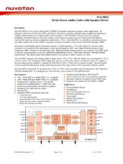
1 Nov. 16, 2015 Page 1 of 56 Rev AN0004 Application Note for 32-bit NuMicro Family Document Information Abstract This Application note describes how to implement hdmi (high-definition multimedia interface) CEC (consumer electronics control) functions as a tv set or a projector that support the HDMI-CEC protocol based on the Timer Capture function of NuMicro family Cortex -M0 M051 and M0518 series microcontrollers (MCUs). Apply to NuMicro M051 and M0518 series which support the Timer Capture function. The information described in this document is the exclusive intellectual property of Nuvoton Technology Corporation and shall not be reproduced without permission from Nuvoton.
2 Nuvoton is providing this document only for reference purposes of NuMicro microcontroller based system design. Nuvoton assumes no responsibility for errors or omissions. All data and specifications are subject to change without notice. For additional information or questions, please contact: Nuvoton Technology Corporation. HDMI-CEC Application Note & Sample code Nov. 16, 2015 Page 2 of 56 Rev AN0004 Table of Contents 1 OVERVIEW .. 5 The Purpose of HDMI-CEC .. 5 2 HDMI-CEC SPECIFICATION ABSTRACT .. 6 Introduction to CEC .. 6 CEC Communication .. 6 6 CEC Format .. 9 CEC Features .. 14 3 TIMER CAPTURE FUNCTION .. 16 Timer Controller .. 16 Timer Controller of M051 Series.
3 16 Timer Controller of M0518 Series .. 17 Timer Event Capture Function .. 18 Use the Timer Capture to Measure the CEC Signal .. 19 4 EXAMPLE code .. 20 Hardware System Structure .. 20 Firmware Description .. 22 Main Function and System Initialization .. 22 Interrupt Handler .. 33 CEC Sub-functions .. 41 Test Results .. 47 Nov. 16, 2015 Page 3 of 56 Rev AN0004 List of Figures Figure 1-1 Home Entertainment Structure .. 5 Figure 2-1 CEC and DDC Line Connections .. 6 Figure 2-2 Physical Addresses within an hdmi Cluster .. 7 Figure 2-3 Physical and Logical Addressing within a hdmi Cluster .. 9 Figure 2-4 CEC Messages in a CEC Feature .. 10 Figure 2-5 Message Structure.
4 10 Figure 2-6 Data Block Format .. 11 Figure 2-7 Header Block Format .. 12 Figure 2-8 Start Bit Timing .. 12 Figure 2-9 Data Bit Timing .. 13 Figure 2-10 Asserted Bit Timing .. 13 Figure 2-11 Typical Scenario for One Touch Play Feature .. 14 Figure 2-12 Typical Scenario for Broadcast (System) Standby Feature .. 15 Figure 2-13 Typical Scenario for Standby Feature to a Specific Device .. 15 Figure 3-1 Clock Source of Timer Controller in M051 Series .. 16 Figure 3-2 Block Diagram of Timer Controller in M051 Series .. 17 Figure 3-3 Clock Source of Timer Controller in M0518 Series .. 17 Figure 3-4 Block Diagram of Timer Controller in M0518 Series .. 18 Figure 3-5 Timing Waveform of Timer 1 Capturing.
5 19 Figure 4-1 Hardware System Structure .. 20 Figure 4-2 Main Function Flow Chart .. 23 Figure 4-3 CEC State Machine .. 34 Figure 4-4 Receiving CEC Flow Chart .. 35 Figure 4-5 Transmitting CEC Flow Chart .. 42 Figure 4-6 Test Result with SONY PS3 .. 48 Figure 4-7 Test Result with Philips DVD Player .. 49 Figure 4-8 Test Result with Google Chromecast .. 50 Figure 4-9 Test Result with Google Chromecast (Continued) .. 51 Nov. 16, 2015 Page 4 of 56 Rev AN0004 List of Tables Table 2-1 Logical Address .. 8 Table 4-1 Pin Function and GPIO Mode .. 21 Table 4-2 CEC Messages .. 54 Nov. 16, 2015 Page 5 of 56 Rev AN0004 1 Overview This Application note describes how to implement hdmi (high-definition multimedia interface) CEC (consumer electronics control) functions as a tv set or a projector that support the HDMI-CEC protocol based on the Timer Capture function of NuMicro family Cortex -M0 M051 and M0518 series microcontroller (MCU).
6 At first, the abstract of HDMI-CEC structure and format from the HDMI-CEC specification will be introduced. Then, the Timer Capture function of M051 series and M0518 series will be briefly explained. Finally, the example code and the results using a tiny EVB board of M0516 LDN or M0518SD2AE chip will be present to demonstrate the HDMI-CEC behavior, and emulated as a tv set or a projector connected with SONY PS3, Philips DVD player and Google Chromecast. The Purpose of HDMI-CEC Figure 1-1 shows the home entertainment structure in universal home. The purpose of CEC is to reduce the remote controllers to control all the hdmi devices connected together through the hdmi cables serially.
7 AVRTVR emote ControlDVD PlayerSONY PS3BD PlayerHDMI CableGoogleChromecast Figure 1-1 Home Entertainment Structure Nov. 16, 2015 Page 6 of 56 Rev AN0004 2 HDMI-CEC Specification Abstract Introduction to CEC CEC is the appendix supplement 1 to the hdmi standard. It is a protocol that provides high-level control functions between all of the various audiovisual products in a user s environment. For more details, refer to the High-Definition Multimedia Interface Specification that is available from CEC Communication Address Physical Address To allow CEC to be able to address specific physical devices and control switches, all devices shall have a physical address.
8 This connectivity has to be worked out whenever a new device is added to the cluster. The physical address discovery process uses only the DDC/EDID (Display Data Channel/Extended Display Identification Data) mechanism and can be applied to all hdmi Sinks and Repeaters, not only to CEC-capable devices. The CEC and DDC connections are shown in Figure 2-1. DDC lineCEC bus Figure 2-1 CEC and DDC Line Connections The CEC line is directly connected to all nodes on the network. After discovering their own physical address, the CEC devices transmit their physical and logical addresses to all other devices, thus allowing any device to create a map of the network.
9 Nov. 16, 2015 Page 7 of 56 Rev AN0004 Physical Address Discovery The physical address of each node is determined through the physical address discovery process. This process is dynamic in that it automatically adjusts physical addresses as required as devices are physically or electrically added or removed from the device tree. All Sinks and Repeaters shall perform the steps of physical address discovery and propagation even if those devices are not CEC-capable. Sources are not required to determine their own physical address unless they are CEC-capable. All addresses are 4 digits long allowing for a 5 device-deep hierarchy.
10 All are identified in the form of in the following description. An example of this is given in Figure 2-1. Figure 2-2 Physical Addresses within an hdmi Cluster Logical Address Each device appearing on the control signal line has a logical address which is allocated to only one device in the system. This address defines a device type as well as being a unique identifier. These are specified in Table 2-1. Logical Address Device 0 TV 1 Recording Device 1 2 Recording Device 2 Nov. 16, 2015 Page 8 of 56 Rev AN0004 3 Tuner 1 4 Playback Device 1 5 Audio System 6 Tuner 2 7 Tuner 3 8 Playback Device 2 9 Recording Device 3 10 Tuner 4 11 Playback Device 3 12 Reserved 13 Reserved 14 Free Use 15 Unregistered (as initiator address) Broadcast (as destination address) Table 2-1 Logical Address All CEC devices have both a physical and logical address, whereas non-CEC devices only have a physical address.