Transcription of NAU8822L 24-bit Stereo Audio Codec with Speaker …
1 NAU8822L Datasheet Rev Page 1 of 97 June, 2016 NAU8822L 24-bit Stereo Audio Codec with Speaker Driver Description The NAU8822L is a low power, high quality Codec for portable and general purpose Audio applications. In addition to precision 24-bit Stereo ADCs and DACs, this device integrates a broad range of additional functions to simplify implementation of complete Audio system solutions. The NAU8822L includes drivers for Speaker , headphone, and differential or Stereo line outputs, and integrates preamps for Stereo differential microphones, significantly reducing external component requirements. Also, a fractional PLL is available to accurately generate any Audio sample rate for the Codec using any commonly available system clock from 8 MHz through 33 MHz. Advanced on-chip digital signal processing includes a 5-band equalizer, a 3-D Audio enhancer, a mixed-signal automatic level control for the microphone or line input through the ADC, and a digital limiter/dynamic-range-compressor (DRC) function for the playback path.
2 Additional digital filtering options are available in the ADC path, to simplify implementation of specific application requirements such as wind noise reduction and speech band enhancement. The digital Audio input/output interface can operate as either a master or a slave. The NAU8822L operates with analog supply voltages from to , while the digital core can operate at to conserve power. The loudspeaker BTL output pair and two auxiliary line outputs can operate using a 5V supply to increase output power capability, enabling the NAU8822L to drive 1 Watt into an external Speaker . Internal register controls enable flexible power saving modes by powering down sub-sections of the chip under software control. The NAU8822L is specified for operation from -40 C to +85 C, and is available in a cost-effective, space-saving 32-lead QFN package. Key Features DAC: 94dB SNR and -84dB THD ( A weighted) ADC: 90dB SNR and -80dB THD ( A weighted) Integrated BTL Speaker driver: 1W into 8 Integrated head-phone driver: 40mW into 16 Integrated programmable microphone amplifier Integrated line input and line output On-chip PLL Integrated DSP with specific functions: 5-band equalizer 3-D Audio enhancement Input automatic level control (ALC/AGC)/limiter Output dynamic-range-compressor/limiter Notch filter and high pass filter Standard Audio interfaces.
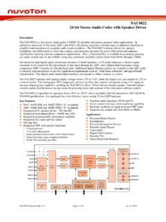
3 PCM and I2S Serial control interfaces with read/write capability Realtime readback of signal level and DSP status Supports any sample rate from 8kHz, 48kHz, 96kHz and 192kHz Applications Personal Media Players Smartphones Personal Navigation Devices Portable Game Players Camcorders Digital Still Cameras Portable TVs Stereo Bluetooth Headsets NAU8822L Datasheet Rev Page 2 of 97 June, 2016 Input MixerRADCDAC FilterVolume ControlLimiterADC FilterVolume ControlHigh Pass & Notch Filters5-band EQ3DI2 SPCMD igital Audio InterfaceSerialControl InterfaceOutput MixerPLLGPIOS tereo Microphone InterfaceLADCLDACRDACM icrophone BiasHeadphones/Line driversBTL SpeakerLMICPLMICNRMICPRMICNLAUXINRAUXINL LINRLINLHPRHPAUXOUT1 AUXOUT2 LSPKOUTRSPKOUTNAU8822L_YG Pinout RLIN/GPIO3 VSSDVDDBRSPKOUTMICBIASVREFLSPKOUT1345678 9101112131415162423222120191817323130292 8272625 LMICPLMICNLLIN/GPIO2 RMICPRMICNFSBCLKADCOUTDACINMCLKVDDCCSB/G PIO1 SCLKVSSSPKAUXOUT2 AUXOUT1 RAUXINLAUXINMODESDIOVDDALHPRHPVSSAVDDSPK 1234567891011121314151624232221201918173 231302928272625 NAU8822L_YG32-lead QFNRoHS Part Number Dimension Package Package Material NAU8822L_YG 5 x 5 mm 32-QFN Green NAU8822L Datasheet Rev Page 3 of 97 June, 2016 Pin Descriptions Pin # Name Type Functionality 1 LMICP Analog Input Left MICP Input (common mode)
4 2 LMICN Analog Input Left MICN Input 3 LLIN/GPIO2 Analog Input / Digital I/O Left Line Input / alternate Left MICP Input / GPIO2 4 RMICP Analog Input Right MICP Input (common mode) 5 RMICN Analog Input Right MICN Input 6 RLIN/GPIO3 Analog Input / Digital I/O Right Line Input/ alternate Right MICP Input / Digital Output In 4-wire mode: Must be used for GPIO3 7 FS Digital I/O Digital Audio DAC and ADC Frame Sync 8 BCLK Digital I/O Digital Audio Bit Clock 9 ADCOUT Digital Output Digital Audio ADC Data Output 10 DACIN Digital Input Digital Audio DAC Data Input 11 MCLK Digital Input Master Clock Input 12 VSSD Supply Digital Ground 13 VDDC Supply Digital Core Supply 14 VDDB Supply Digital Buffer (Input/Output) Supply 15 CSB/GPIO1 Digital I/O 3-Wire MPU Chip Select or GPIO1 multifunction input/output 16 SCLK Digital Input 3-Wire MPU Clock Input / 2-Wire MPU Clock Input 17 SDIO Digital I/O 3-Wire MPU Data Input / 2-Wire MPU Data I/O 18 MODE Digital Input Control Interface Mode Selection Pin 19 LAUXIN Analog Input Left Auxiliary Input 20 RAUXIN Analog Input Right Auxiliary Input 21 AUXOUT1 Analog Output Headphone Ground / Mono Mixed Output / Line Output 22 AUXOUT2 Analog Output Headphone Ground / Line Output 23 RSPKOUT Analog Output BTL Speaker Positive Output or Right high current output 24 VSSSPK Supply Speaker Ground (ground pin for RSPKOUT, LSPKOUT, AUXOUT2 and AUXTOUT1 output drivers ) 25 LSPKOUT Analog Output BTL Speaker Negative Output or Left high current output 26 VDDSPK Supply Speaker Supply (power supply pin for RSPKOUT, LSPKOUT, AUXOUT2 and AUXTOUT1 output drivers )
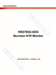
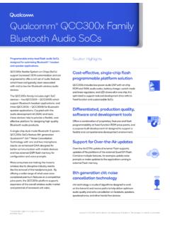
5 27 VREF Reference Decoupling for Midrail Reference Voltage 28 VSSA Supply Analog Ground 29 RHP Analog Output Headphone Positive Output / Line Output Right 30 LHP Analog Output Headphone Negative Output / Line Output Left 31 VDDA Supply Analog Power Supply 32 MICBIAS Analog Output Microphone Bias NAU8822L Datasheet Rev Page 4 of 97 June, 2016 LDACHPFALCN otchFilterLimiter5 Band EQ3D ALC Control RMIXLMIXRDACLDACRINMIXRMIXLMIXLDACLINMIX RMAINMIXERLMAINMIXERAUX1 MIXERAUX2 MIXERLADCMIX/BOOSTRADCMIX/BOOSTRINMIXLIN MIXRSPKSUBMIXERAUXOUT1 AUXOUT2 LHPRHPLSPKOUTRSPKOUTLAUXINRAUXINLMICNLMI CPLLINRMICNRMICPRLINVDDBVDDCVSSDVDDAVSSA VDDSPKVSSSPKBCLKFSADCOUTDACINCONTROL INTERFACE(2-, 3- and 4-wire)MCLKSCLKSDIOCSB/GPIO1 MODEVREFRRVDDAMICROPHONE + + + + INTERFACE(PCM/IIS)PLL879101116171518-+-+ Normal-6dBRDACRADCRADC Figure 1: NAU8822L Block Diagram NAU8822L Datasheet Rev Page 5 of 97 June, 2016 Electrical Characteristics Conditions: VDDC = , VDDA = VDDB = VDDSPK = (VDDSPK = *VDDA when Boost), MCLK = , TA = +25 C, 1kHz signal, fs = 48kHz, 24-bit Audio data, 64X oversampling rate, unless otherwise stated.
6 Parameter Symbol Comments/Conditions Min Typ Max Units Analog to Digital Converter (ADC) Full scale input signal 1 VINFS PGABST = 0dB PGAGAIN = 0dB 0 Vrms dBV Signal-to-noise ratio SNR Gain = 0dB, A-weighted 90 dB Total harmonic distortion 2 THD+N Input = -3dB FS input -80 dB Channel separation 1kHz input signal 106 dB Digital to Analog Converter (DAC) driving RHP / LHP with 10k / 50pF load Full-scale output Gain paths all at 0dB gain VDDA / Vrms Signal-to-noise ratio SNR A-weighted 88 94 dB Total harmonic distortion 2 THD+N RL = 10k ; full-scale signal -84 dB Channel separation 1kHz input signal 98 dB Output Mixers Maximum PGA gain into mixer +6 dB Minimum PGA gain into mixer -15 dB PGA gain step into mixer Guaranteed monotonic 3 dB Speaker Output (RSPKOUT / LSPKOUT with 8 bridge-tied-load) Full scale output 4 SPKBST = 1, VDDSPK=VDDA VDDA / Vrms SPKBST = 0 VDDSPK= * VDDA (VDDA / ) * Vrms Total harmonic distortion 2 THD+N Po = 200mW, VDDSPK= -64 dB Po = 320mW, VDDSPK = -65 dB Po = 860mW, VDDSPK = * VDDA -60 dB Po = 1000mW, VDDSPK = * VDDA -37 dB Signal-to-noise ratio SNR VDDSPK = 98 dB VDDSPK= * VDDA 92 dB Power supply rejection ratio (50Hz - 22kHz) PSRR VDDSPK = 85 dB VDDSPK = * VDDA 79 dB Analog Outputs (RHP / LHP.)
7 RSPKOUT / LSPKOUT) Maximum programmable gain +6 dB Minimum programmable gain -57 dB Programmable gain step size Guaranteed monotonic 1 dB Mute attenuation 1kHz full scale signal 85 dB NAU8822L Datasheet Rev Page 6 of 97 June, 2016 Electrical Characteristics, cont d. Conditions: VDDC = , VDDA = VDDB = VDDSPK = (VDDSPK = *VDDA when Boost), MCLK = , TA = +25 C, 1kHz signal, fs = 48kHz, 24-bit Audio data, unless otherwise stated. Parameter Symbol Comments/Conditions Min Typ Max Units Headphone Output (RHP / LHP with 32 load) 0dB full scale output voltage VDDA / Vrms Signal-to-noise ratio SNR A-weighted 96 dB Total harmonic distortion 2 THD+N RL = 16 , Po = 20mW, VDDA = -84 dB RL = 32 , Po = 20mW, VDDA = -86 dB AUXOUT1 / AUXOUT2 with 10k / 50pF load Full scale output AUX1 BST = 0 AUX2 BST = 0 VDDSPK=VDDA VDDA / Vrms AUX1 BST = 1 AUX2 BST = 1 VDDSPK= *VDDA (VDDA / ) * Vrms Signal-to-noise ratio SNR 93 dB Total harmonic distortion 2 THD+N -86 dB Channel separation 1kHz signal 104 dB Power supply rejection ratio (50Hz - 22kHz) PSRR VDDSPK = 85 dB VDDSPK = * VDDA 79 dB Microphone Inputs (LMICP, LMICN, RMICP, RMICN, LLIN, RLIN) and Programmable Gain Amplifier (PGA)
8 Full scale input signal 1 PGABST = 0dB PGAGAIN = 0dB 0 Vrms dBV Programmable gain -12 dB Programmable gain step size Guaranteed Monotonic dB Mute Attenuation 120 dB Input resistance Inverting Input PGA Gain = PGA Gain = 0dB PGA Gain = -12dB Non-inverting Input 47 75 94 k k k k Input capacitance 10 pF PGA output noise 0 to 20kHz, Gain set to 120 V Input Boost Mixer Gain boost Boost disabled Boost enabled 0 20 dB dB Gain range LLIN / RLIN or LAUXIN / RAUXIN to boost/mixer -12 6 dB Gain step size to boost/mixer 3 dB Auxiliary Analog Inputs (LAUXIN, RAUXIN) Full scale input signal 1 Gain = 0dB 0 Vrms dBV Input resistance Aux direct-to-out path, only Input gain = + Input gain = Input gain = -12dB 20 40 159 k k k Input capacitance 10 pF NAU8822L Datasheet Rev Page 7 of 97 June, 2016 Electrical Characteristics, cont d. Conditions: VDDC = , VDDA = VDDB = VDDSPK = (VDDSPK = *VDDA when Boost), MCLK = , TA = +25 C, 1kHz signal, fs = 48kHz, 24-bit Audio data, unless otherwise stated.
9 Parameter Symbol Comments/Conditions Min Typ Max Units Automatic Level Control (ALC) & Limiter: ADC path only Target record level dBFS Programmable gain -12 dB Gain hold time 3 tHOLD Doubles every gain step, with 16 steps total 0 / / / .. / 43691 ms Gain ramp-up (decay) 3 tDCY ALC Mode ALC = 0 4 / 8 / 16 / .. / 4096 ms Limiter Mode ALC = 1 1 / 2 / 4 / .. / 1024 ms Gain ramp-down (attack) 3 tATK ALC Mode ALC = 0 1 / 2 / 4 / .. / 1024 ms Limiter Mode ALC = 1 / / 1 / .. / 128 ms Mute Attenuation 120 dB Microphone Bias Bias voltage VMICBIAS See Figure 3 , , , , , , or VDDA VDDA Bias current source IMICBIAS 3 mA Output noise voltage Vn 1kHz to 20kHz 14 nV/ Hz Digital Input/Output Input HIGH level VIL * VDDB V Input LOW level VIH * VDDB V Output HIGH level VOH ILoad = 1mA * VDDB V Output LOW level VOL ILoad = -1mA * VDDB V Input capacitance 10 pF Notes 1. Full Scale is relative to the magnitude of VDDA and can be calculated as FS = 2.
10 Distortion is measured in the standard way as the combined quantity of distortion products plus noise. The signal level for distortion measurements is at 3dB below full scale, unless otherwise noted. 3. Time values scale proportionally with MCLK. Complete descriptions and definitions for these values are contained in the detailed descriptions of the ALC functionality. 4. with default register settings, VDDSPK should be (but not exceeding maximum recommended operating voltage) to optimize available dynamic range in the AUXOUT1 and AUXOUT2 line output stages. Output DC bias level is optimized for VDDSPK = (boost mode) and VDDA = 5. Unused analog input pins should be left as no-connection. 6. Unused digital input pins should be tied to ground. NAU8822L Datasheet Rev Page 8 of 97 June, 2016 Absolute Maximum Ratings Condition Min Max Units VDDB, VDDC, VDDA supply voltages + V VDDSPK supply voltage (default register configuration) + V VDDSPK supply voltage (optional low voltage configuration) + V Core Digital Input Voltage range VSSD VDDC + V Buffer Digital Input Voltage range VSSD VDDB + V Analog Input Voltage range VSSA VDDA + V Industrial operating temperature -40 +85 C Storage temperature range -65 +150 C CAUTION: Do not operate at or near the maximum ratings listed for extended periods of time.