Transcription of AUXOUT2 RLIN 24-bit Stereo Audio Codec with …
1 NAU8822. 24-bit Stereo Audio Codec with speaker Driver Description The NAU8822 is a low power , high quality Codec for portable and general purpose Audio applications. In addition to precision 24-bit Stereo ADCs and DACs, this device integrates a broad range of additional functions to simplify implementation of complete Audio system solutions. The NAU8822 includes drivers for speaker , headphone, and differential or Stereo line outputs, and integrates preamps for Stereo differential microphones, significantly reducing external component requirements. Also, a fractional PLL is available to accurately generate any Audio sample rate for the Codec using any commonly available system clock from 8 MHz through 33 MHz.
2 Advanced on-chip digital signal processing includes a 5-band equalizer, a 3-D Audio enhancer, a mixed-signal automatic level control for the microphone or line input through the ADC, and a digital limiter/dynamic-range- compressor (DRC) function for the playback path. Additional digital filtering options are available in the ADC path, to simplify implementation of specific application requirements such as wind noise reduction and speech band enhancement. The digital Audio input/output interface can operate as either a master or a slave. The NAU8822 operates with analog supply voltages from to , while the digital core can operate at to conserve power .
3 The loudspeaker BTL output pair and two auxiliary line outputs can operate using a 5V supply to increase output power capability, enabling the NAU8822 to drive 1 Watt into an external speaker . Internal register controls enable flexible power saving modes by powering down sub-sections of the chip under software control. The NAU8822 is specified for operation from -40 C to +85 C, and is available with full automotive AEC-/Q100 &. TS16949 qualification. It is packaged in a cost-effective, space-saving 32-lead QFN package. Key Features Standard Audio interfaces: PCM and I2S. DAC: 94dB SNR and -84dB THD ( A weighted) Serial control interfaces with read/write capability ADC: 90dB SNR and -80dB THD ( A weighted) Realtime readback of signal level and DSP status Integrated BTL speaker driver: 1W into 8 Supports any sample rate from 8kHz to 48kHz Integrated head-phone driver: 40mW into 16 Applications Integrated programmable microphone amplifier Integrated line input and line output Personal Media Players On-chip PLL Smartphones Integrated DSP with specific functions.
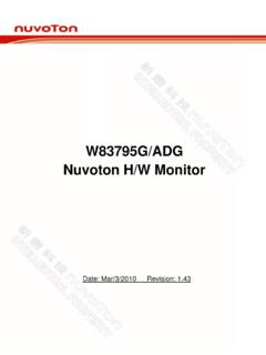
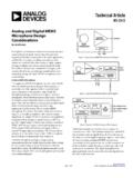
4 Personal Navigation Devices 5-band equalizer Portable Game Players 3-D Audio enhancement Camcorders Input automatic level control (ALC/AGC)/limiter Digital Still Cameras Output dynamic-range-compressor/limiter Portable TVs Notch filter and high pass filter Stereo Bluetooth Headsets Headphones/. LAUXIN Line drivers AUXOUT2 . RAUXIN. ADC Filter LLIN LADC DAC Filter LDAC AUXOUT1. Volume Volume RLIN Control Control LHP. High Pass &. Stereo Input RADC Limiter RDAC Output LMICN Notch Filters Microphone Mixer Mixer RHP. LMICP Interface 5-band EQ. BTL speaker RMICN 3D. LSPKOUT. RMICP. RSPKOUT. Digital Audio Interface Serial Microphone Control Bias GPIO PLL I2S PCM Interface NAU8822 AYG.
5 NAU8822 Datasheet Rev Page 1 of 91 Jan 15, 2016. Pinout LSPKOUT. MICBIAS. VDDSPK. VDDA. VSSA. VREF. RHP. LHP. 27. 29. 28. 26. 25. 32. 31. 30. 32. 31. 30. 29. 28. 27. 26. 25. LMICP 1 24. 24 VSSSPK. LMICN 2 23. 23 RSPKOUT. LLIN/GPIO2 3 NAU8822_YG 22. 22 AUXOUT2 . RMICP 4. 32-lead QFN 21. 21 AUXOUT1. RMICN 5. RoHS 20. 20 RAUXIN. RLIN/GPIO3 6 19. 19 LAUXIN. FS 7 18. 18 MODE. BCLK 8 17. 17 SDIO. 10. 11. 12. 13. 14. 15. 16. 9. ADCOUT. DACIN. MCLK. VSSD. VDDC. VDDB. CSB/GPIO1. SCLK. Package Part Number Dimension Package Material NAU8822_YG 5 x 5 mm 32-QFN Green NAU8822 Datasheet Rev Page 2 of 91 Jan. 15, 2016. Pin Descriptions Pin # Name Type Functionality 1 LMICP Analog Input Left MICP Input (common mode).
6 2 LMICN Analog Input Left MICN Input 3 LLIN/GPIO2 Analog Input / Left Line Input / alternate Left MICP Input / GPIO2. Digital I/O. 4 RMICP Analog Input Right MICP Input (common mode). 5 RMICN Analog Input Right MICN Input 6 RLIN/GPIO3 Analog Input / Right Line Input/ alternate Right MICP Input / Digital Output Digital I/O In 4-wire mode: Must be used for GPIO3. 7 FS Digital I/O Digital Audio DAC and ADC Frame Sync 8 BCLK Digital I/O Digital Audio Bit Clock 9 ADCOUT Digital Output Digital Audio ADC Data Output 10 DACIN Digital Input Digital Audio DAC Data Input 11 MCLK Digital Input Master Clock Input 12 VSSD Supply Digital Ground 13 VDDC Supply Digital Core Supply 14 VDDB Supply Digital Buffer (Input/Output) Supply 15 CSB/GPIO1 Digital I/O 3-Wire MPU Chip Select or GPIO1 multifunction input/output 16 SCLK Digital Input 3-Wire MPU Clock Input / 2-Wire MPU Clock Input 17 SDIO Digital I/O 3-Wire MPU Data Input / 2-Wire MPU Data I/O.
7 18 MODE Digital Input Control Interface Mode Selection Pin 19 LAUXIN Analog Input Left Auxiliary Input 20 RAUXIN Analog Input Right Auxiliary Input 21 AUXOUT1 Analog Output Headphone Ground / Mono Mixed Output / Line Output 22 AUXOUT2 Analog Output Headphone Ground / Line Output 23 RSPKOUT Analog Output BTL speaker Positive Output or Right high current output 24 VSSSPK Supply speaker Ground (ground pin for RSPKOUT, LSPKOUT, AUXOUT2 and AUXTOUT1 output drivers ). 25 LSPKOUT Analog Output BTL speaker Negative Output or Left high current output 26 VDDSPK Supply speaker Supply ( power supply pin for RSPKOUT, LSPKOUT, AUXOUT2 and AUXTOUT1 output drivers ).
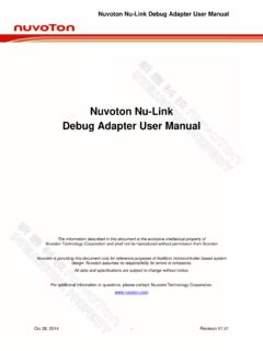
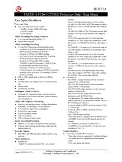
8 27 VREF Reference Decoupling for Midrail Reference Voltage 28 VSSA Supply Analog Ground 29 RHP Analog Output Headphone Positive Output / Line Output Right 30 LHP Analog Output Headphone Negative Output / Line Output Left 31 VDDA Supply Analog power Supply 32 MICBIAS Analog Output Microphone Bias NAU8822 Datasheet Rev Page 3 of 91 Jan. 15, 2016. VDDB VDDC VSSD VDDA VSSA VDDSPK VSSSPK. 14 13 12 31 28 26 24 Normal 19. LAUXIN RINMIX -6dB. LADC LINMIX LDAC NAU8822 Datasheet Rev MIX/BOOST + AUXOUT1. AUX1 21. MIXER. RDAC. 2. LMICN - LMIX 1 RADC LDAC AUXOUT2 . + LMICP + 22. 3. LLIN LMAIN. HPF MIXER. ALC. ALC Control Limiter 5 Notch LHP. RMICN - Filter 30.
9 4. RMICP + RMAIN. 6 MIXER. Page 4 of 91. RLIN. RADC RDAC RMIX. RHP. 29. 20. RAUXIN. VDDA RADC 5 Band EQ LINMIX. MIX/BOOST 3D. 27 R. LDAC. Figure 1: NAU8822 Block Diagram VREF. R . RINMIX LMIX + LSPKOUT. AUX2 25. MIXER. 32 MICROPHONE. MICBIAS BIAS. + RSPKOUT. 23. Audio INTERFACE CONTROL INTERFACE RMIX. PLL RSPK. (PCM/IIS) (2-, 3- and 4-wire). SUBMIXER. 8 7 9 10 11 16 17 15 18. BCLK FS ADCOUT DACIN MCLK SCLK SDIO CSB/ MODE. GPIO1. Jan. 15, 2016. Electrical Characteristics Conditions: VDDC = , VDDA = VDDB = VDDSPK = (VDDSPK = *VDDA when Boost), MCLK = , TA = +25 C, 1kHz signal, fs = 48kHz, 24-bit Audio data, 64X oversampling rate, unless otherwise stated.
10 Parameter Symbol Comments/Conditions Min Typ Max Units Analog to Digital Converter (ADC). Full scale input signal 1 VINFS PGABST = 0dB Vrms PGAGAIN = 0dB 0 dBV. Signal-to-noise ratio SNR Gain = 0dB, A-weighted tbd 90 dB. Total harmonic distortion 2 THD+N Input = -3dB FS input -80 tbd dB. Channel separation 1kHz input signal 103 dB. Digital to Analog Converter (DAC) driving RHP / LHP with 10k / 50pF load Full-scale output Gain paths all at 0dB gain VDDA / Vrms Signal-to-noise ratio SNR A-weighted 88 94 dB. Total harmonic distortion 2 THD+N RL = 10k ; full-scale signal -84 tbd dB. Channel separation 1kHz input signal 96 dB. Output Mixers Maximum PGA gain into mixer +6 dB.