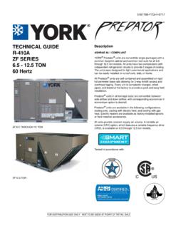
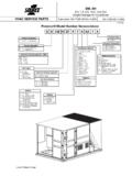
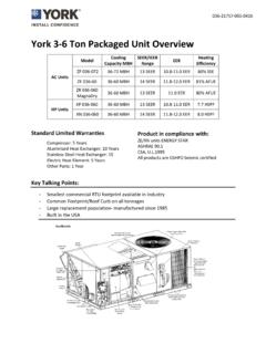
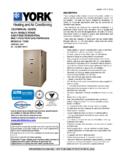
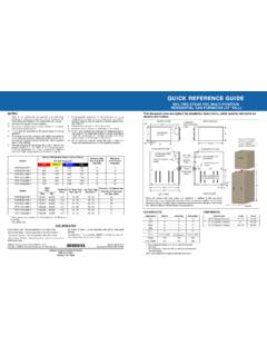
Transcription of HIGH ALTITUDE CONVERSION M-1HA0802 …
1 GENERALThis instruction is intended for the CONVERSION of new equip-ment only, for operation at altitudes greater than 2,000 ft. abovesea level. Follow the basic unit installation instruction for allother aspects of the unit installations above 2,000 ft. must be field derated asrequired by the National Fuel Gas Code, ANSI (latestedition), or in Canada, CAN/CGA or .2 and all otherapplicable local codes and utility instruction provides the necessary information to selectand install the proper orifice for your specific application.
2 Datais provided for both natural gas and propane (LP).WARNING: Improper installation , adjustment service, or main-tenance can cause injury or property dam-age;therefore, only a qualified installer or qualifiedservice personnel should perform this SIZE SELECTIONA number of factors determine the correct orifice usage for yourapplication. These factors include the original orifice sizing,BTU content of the gas and the standard orifice used on some models is a #43 orifice whileon other models a #40 orifice is standard.
3 To select the propertable to identify the correct derate orifice, identify the correctorifice shipped with your unit on the unit rating plate. For natural gas applications, contact your gas supplier for theactual BTU content (heating value) of the fuel provided at youraltitude. Table 1 indicates various BTU content fuels. Use theBTU heating value that is nearest to your value. Read acrossthe selected table from the standard orifice to the ALTITUDE foryour application and the note the new orifice : If your utility provides a heating gas value of 900 , at an ALTITUDE of 7000 feet a #44 orifice will provide the correct firing rate.
4 If a #43 orifice isyour standard orfice supplied with the propane (LP) applications, Use Table 2 to select the properhigh ALTITUDE orifice : The furnace must first be converted to use propane (LP) through the use of the standard propane CONVERSION kit selecting the proper orifice size for your application, seeTable 3 that indicates the part number for your required orificenumber. The orifices may be obtained through your localSource 1 Parts Distribution Center. WARNING: Make sure both gas and power supplies are shut off before high ALTITUDE orifices should be changed by the followingprocedure:1.
5 Turn "OFF" all electrical power and gas supply to the Carefully remove the wires from the gas valve and notethere location so they may properly replaced. Remove thefour screws that hold the manifold to the manifold supportbracket and slide the manifold and orifices back out of Remove the main burner orifices from the manifold anddiscard Install the derate main burner orifices in the manifold andtighten them. After installing a new orifice in each location,any leftover orifices may be Reinstall the manifold in the assembly by reversing theremoval Install the high ALTITUDE CONVERSION labels as described inthe LABELS sections of this Refer to the unit installation instructions to complete theinstallation before continuing with these ALTITUDE APPLICATIONCONVERSION INSTRUCTIONMODEL 1ha0802 Supersedes.
6 (995) (496)035-13940 FOR SINGLE PACKAGE GAS / ELECTRIC AIR THRU 5 TONCONTENTS OF KITITEM and Modify Label21035-13941-000 Accessory Instruction Form31035-13942-000 Accessory Instruction Form(French)WARNING: For units, installation must be made in accordance with American Na-tional Standard National Fuel Gas Code, ANSI - latest edition, unless supersededby local codes. For Canadian installations, the CONVERSION shall be carried out in accord-ance with the requirements of the Provincial authorities having jurisdiction and in ac-cordance with the and.
7 2 installation : This CONVERSION kit is to be installed by a qualified service agency in accord-ance with the manufacturer s instructions and all applicable codes and requirements ofthe authority having jurisdiction. If the information in these instructions is not followedexactly, a fire, explosion or production of carbon monoxide may result causing propertydamage, personal injury or loss of life. The qualified agency performing this work as-sumes responsibility for the proper CONVERSION of this appliance with this AND ADJUSTMENTSThe following tests must be performed at the time of conversionfollowing completion of the Connect a manometer to the pressure tap in the gas a power supply and a gas supply to the unit, if notalready Turn on the gas supply and bleed air from the gas supplylines at a point as close to the inlet or the gas valve as ispractical.
8 WARNING: Make sure the space is free of gas before Turn the gas valve control knob to the ON Make sure unit electrical disconnect switch is in the Set the room thermostat to call for Turn unit electrical disconnect switch to ON. The combus-tion blower should start and the hot surface igniter shouldstart After air has been purged from the gas supply line, ignitionshould occur. Shortly after ignition, the manifold pressurecan be checked on the manometer. Main burner ignitionmay be delayed on the first ignition cycle due to air in thegas Adjust manifold pressure as shown below.
9 This setting willresult in an input which is properly derated for your gas must be within the range Observe several ignition cycles. All main burners mustignite without delayed ignition or burning at the orifices. Ifdelayed ignition is observed, verify that the ignitor/pilot isproperly mounted (not loose or crooked on bracket, andthat bracket screws are not loose).10. If burning at the orifices, excessive yellow tipping, orexcessive noise is observed during any phase of mainburner operation, verify unit With the main burners ignited, check for gas leaks, espe-cially in the following locations: gas valve inlet and outletconnections, manifold union in the burner compartment,and main burner orifices where they thread into the mani-fold.
10 Repair any leaks found and : Do not use an open flame or any source of ignitionto check for Operate the furnace for 15 minutes and measure thesupply and return air temperatures. Verify that the tem-perature rise (supply air - return air rise) is within theallowable range. See the unit data plate for the mini-mum/maximum allowable temperature rise. If the meas-ured rise is in excess of the maximum shown on the dataplate, a higher blower speed must be selected. See theunit wiring diagram to make this With the main burners off, disconnect the manometer andreplace the plug.