Transcription of High-Efficiency Controller for Boost, SEPIC, and Flyback ...
1 LM3481 VINISENCOMPFBAGNDUVLOVCCDRPGNDFA/SYNC/SD ++VIN = 5 VVOUT = 12VR7121 k:R8121 k:CC82 nFC8 390 k:RF220 k:RF1169 k:RSEN 20 m:CSEN1 nF1 PFCIN1, CIN2 150 PHIOUT = , COUT2 150 PFC9D1Q1 ProductFolderSample &BuyTechnicalDocumentsTools &SoftwareSupport &CommunityAn IMPORTANTNOTICEat the end of this datasheetaddressesavailability,warranty, changes,use in safety-criticalapplications,intellectual propertymattersand ,LM3481-Q1 SNVS346F NOVEMBER2007 REVISEDNOVEMBER2014LM3481/ -Q1 high -EfficiencyControllerfor Boost, SEPICand FlybackDC-DCConverters11 Features1 LM3481 QMMare Automotive-GradeProductsThatare AEC-Q100 Grade1 Qualified( 40 C to+125 C OperatingJunctionTemperature) 10-LeadVSSOPP ackage InternalPush-PullDriverWith1-A PeakCurrentCapability CurrentLimitand ThermalShutdown FrequencyCompensationOptimizedWithaCapac itorand a Resistor InternalSoftstart CurrentModeOperation AdjustableUndervoltageLockoutWithHystere sis PulseSkippingat LightLoads Key Specifications WideSupplyVoltageRangeof to 48 V 100-kHzto 1-MHzAdjustableandSynchronizableClockFre quency (OverTemperature)InternalReference 10- A ShutdownCurrent(OverTemperature)
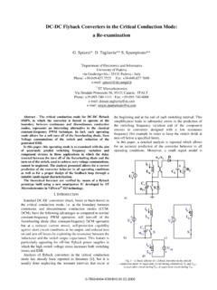
2 Createa CustomDesignUsingthe LM3481withthe WEBENCHP owerDesigner2 Applications AutomotiveStart-StopApplications AutomotiveADASD riverInformation One Cell/TwoCell Li-ionBatteryPoweredPortableBluetoothAud ioSystems Notebooks,PDAs,DigitalCameras,and OtherPortableApplications OfflinePowerSupplies Set-TopBoxes Boostfor AudioAmplifiers3 DescriptionTheLM3481deviceis a versatileLow-SideN-FEThigh-performanceco ntrollerfor deviceis designedfor use in Boost, SEPICandFlybackconvertersandtopolo giesrequiringa low-sideFETas the LM3481devicecan be operatedat very high the LM3481devicecan be adjustedtoany valuebetween100kHzand1 MHzby usingasingleexternalresistoror by synchronizingit to transientresponsein additionto can beprogrammedwith a built-inprotectionfeaturessuchas thermalshutdown,short-circuitprotectiona nd totalsupplycurrentto 5 A inrushcurrentat designand,ifneededfor specificapplications,can be increasedusinga (1)PARTNUMBERPACKAGEBODYSIZE(NOM)LM3481 VSSOP(10) (1) For all availablepackages,see the orderableaddendumatthe end of the LM3481 Typical5V to 12V BoostConverterApplication2LM3481,LM3481- Q1 SNVS346F NOVEMBER2007 :LM3481LM3481-Q1 SubmitDocumentationFeedbackCopyright 2007 2014,TexasInstrumentsIncorporatedTableof Contents1 Pin Configurationand Applicationand Deviceand Mechanical,Packaging,and RevisionHistoryChangesfromRevisionE (April2012)to RevisionFPage AddedPin Configurationand Functionssection,HandlingRatingtable,Fea tureDescriptionsection,DeviceFunctionalM odes,Applicationand Implementationsection,PowerSupplyRecomme ndationssection,Layoutsection,Deviceand DocumentationSupportsection,andMechanica l,Packaging,and , NOVEMBER2007 REVISEDNOVEMBER2014 ProductFolderLinks.
3 LM3481LM3481-Q1 SubmitDocumentationFeedbackCopyright 2007 2014,TexasInstrumentsIncorporated5 Pin Configurationand Functions10-PinVSSOPP ackageTop ViewPin Voltagegeneratedacrossan externalsenseresistoris fed into this A resistordividerfromVINto groundis connectedto the UVLOpin. Theratioof theseresistancesdeterminethe inputvoltagewhichallowsswitchingand the A resistorand capacitorcombinationconnectedto this pin providescompensationfor the Invertinginputof the Internalbias connectedto PGNDat a ,synchronization,and shutdownpin. A resistorconnectedfromthis pin to groundsets the externalclocksignalat this pin will synchronizethe controllertothe frequencyof the high levelon this pin for 30 s will turn the deviceoff and the devicewill thendraw5 A fromthe connectedto AGNDat a of the IC. The gateof the externalMOSFET shouldbe connectedto this A bypasscapacitormustbe connectedfromthis pin to not bias ,LM3481-Q1 SNVS346F NOVEMBER2007 :LM3481LM3481-Q1 SubmitDocumentationFeedbackCopyright 2007 2014,TexasInstrumentsIncorporated(1)Abso luteMaximumRatingsare limitsbeyondwhichdamageto the devicemay whichthe deviceis intendedto be functional,but doesnot ensuredspecificationsand test conditions,see theElectricalCharacteristics.
4 The ensuredspecificationsapplyonly for the test conditions.(2)Part is MSL1-260 Cqualified6 (unlessotherwisenoted)(1)MINMAXUNITVINPi n Voltage Voltage Voltage Voltage Voltage Voltage Voltage Voltage 400600mVPeakDriverOutputCurrent1 APowerDissipationInternallyLimitedJuncti onTemperature150 CLeadTemperature(onlyappliestooperatingc onditions)DGSP ackage220 CPeakBodyTemperature(2)260 C(1)JEDEC documentJEP155statesthat 500-VHBM allowssafe manufacturingwith a standardESDcontrolprocess.(2)JEDEC documentJEP157statesthat 250-VCDM allowssafe manufacturingwith a :LM3481 MINMAXUNITTstgStoragetemperaturerange 65150 CV(ESD)ElectrostaticdischargeHumanbodymo del(HBM),per ANSI/ESDA/JEDECJS-001,allpins(1) 2000+2000 VChargeddevicemodel(CDM),per JEDEC specificationJESD22-C101,all pins(2) 750+750(1)AECQ100-002indicatesHBMstressi ngis donein accordancewith the ANSI/ :LM3481-Q1 MINMAXUNITTstgStoragetemperaturerange 65150 CV(ESD)ElectrostaticdischargeHumanbodymo del(HBM),per AECQ100-002(1) 2000+2000 VChargeddevicemodel(CDM),perAECQ100-011 Cornerpins (1, 5, 6,and 10) 750+750 Otherpins 750+ 40125 CSwitchingFrequencyRange1001kHz/MHz5LM34 81, NOVEMBER2007 REVISEDNOVEMBER2014 ProductFolderLinks.
5 LM3481LM3481-Q1 SubmitDocumentationFeedbackCopyright 2007 2014,TexasInstrumentsIncorporated(1)For moreinformationabouttraditionaland new thermalmetrics,see theIC PackageThermalMetricsapplicationreport, (1)LM3481 UNITVSSOP10 PINSR C/WR JC(top)Junction-to-case(top) JC(bot)Junction-to-case(bottom)thermalre sistance-(1)The drivepin voltage,VDR, is equalto the inputvoltagewheninputvoltageis less than6 V. VDRis equalto 6 V whenthe inputvoltageis greaterthanor equalto 6 V.(2)For this test, the FA/SYNC/SDPin is pulledto groundusinga 40-k 12 V, RFA= 40 k , TJ= 25 C, V, VIN 48 V, VIN 48 V, 40 C TJ 125 VLINEF eedbackVoltageLine VIN 48 VLOADO utputVoltageLoadRegulationIEAOS ource/Sink , 40 C TJ 125 AEnabled, 40 C TJ 125 CurrentSinkVFB= 0V640 AVCOMPVFB= 40 k 475kHzRFA= 40 k , 40 C TJ 125 C406550 Vsync-HIThresholdfor SynchronizationonFA/ SynchronizationonFA/ (ON)DriverSwitchOn Resistance(top)IDR= ,VIN= 5 V4 RDS2(ON)DriverSwitchOn Resistance(bottom)IDR= VDR (max)MaximumDriveVoltageSwing(1)VIN< 6 VVINVVIN 6V6 DmaxMaximumDutyCycleRFA=40 k 81%85%tmin(on)MinimumOn Time250363nsworstcaseovertemperature571n sISUPPLYS upplyCurrent(switching)See(2) (2), 40 C TJ 125 ,LM3481-Q1 SNVS346F NOVEMBER2007.
6 LM3481LM3481-Q1 SubmitDocumentationFeedbackCopyright 2007 2014,TexasInstrumentsIncorporatedElectri calCharacteristics(continued)VIN= 12 V, RFA= 40 k , TJ= 25 C, (3)For this test, the FA/SYNC/SDPin is pulledto 3 V usinga 40-k resistor.(4)The overvoltageprotectionis specifiedwith respectto the is becausethe overvoltagethresholdcan be calculatedby addingthe feedbackvoltage(VFB) to the overvoltageprotectionspecification.(5)Th e FA/SYNC/SDpin shouldbe pulledto VINthrougha resistorto turn the regulatoroff. The voltageon the FA/SYNC/SDpin mustbeabovethe max limit for the Output= Highlongerthan30 s to keepthe regulatoroff and mustbe belowthe minimumlimit for Output=Low to keepthe ShutdownModeVFA/SYNC/SD= 3 V(3), VIN= 12 V9 AVFA/SYNC/SD= 3 V(3), VIN= 12 V, 40 C TJ 125 C15 VFA/SYNC/SD= 3 V(3), VIN= 5 V5 VFA/SYNC/SD= 3 V(3), VIN= 5 V, 40 C TJ 125 C10 VSENSEC urrentSenseThresholdVoltage160mV 40 C TJ 125 C100190 VSCOverLoadCurrentLimitSenseVoltage220mV 40 C TJ 125 C157275 VSLI nternalCompensationRampVoltage90mVVOVPO utputOver-voltageProtection(withrespectt o feedbackvoltage)(4)VCOMP= V85mVVCOMP= V, 40 C TJ 125 C26135 VOVP(HYS)OutputOver-VoltageProtectionHys teresisVCOMP= V70mVVCOMP= V, 40 C TJ 125 C28106 GmErrorAmplifierTransconductanceVCOMP= V450 mhoVCOMP= V, 40 C TJ 125 C216690 AVOLE rrorAmplifierVoltageGainVCOMP= V, IEAO= 100 A(Source/Sink)60V/VVCOMP= V, IEAO= 100 A(Source/Sink)
7 , 40 C TJ 125 C3566 IEAOE rrorAmplifierOutputCurrent(Source/Sink)S ource,VCOMP= V, VFB= V640 ASource,VCOMP= V, VFB= V, 40 C TJ 125 C475837 Sink,VCOMP= V, VFB= V65 ASink,VCOMP= V, VFB= V, 40 C TJ 125 C31100 VEAOE rrorAmplifierOutputVoltageSwingUpperLimi t:VFB= 0 V, :VFB= 0 V, COMPPinFloating, 40 C TJ 125 :VFB= :VFB= V, 40 C TJ 125 V, COMPPin RiseTimeCgs = 3000pf, VDR= 0 V to 3 V25nstfDrivePin Fall TimeCgs = 3000pf, VDR= 3 V to 0 V25nsVSDS hutdownsignalthreshold(5)FA/SYNC/SDpinOu tput= high (Shutdown) high (Shutdown), 40 C TJ 125 Low (Enable) Low (Enable), 40 C TJ 125 , NOVEMBER2007 REVISEDNOVEMBER2014 ProductFolderLinks:LM3481LM3481-Q1 SubmitDocumentationFeedbackCopyright 2007 2014,TexasInstrumentsIncorporatedElectri calCharacteristics(continued)VIN= 12 V, RFA= 40 k , TJ= 25 C, CurrentFA/SYNC/SDpinVSD= 5 V 1 AVSD= 0 V20 TSDT hermalShutdown165 CTshThermalShutdownHysteresis10 C8LM3481,LM3481-Q1 SNVS346F NOVEMBER2007 :LM3481LM3481-Q1 SubmitDocumentationFeedbackCopyright 2007 2014, ,VIN= 12 V, TJ= 25 CompPin Voltagevs.
8 LoadCurrentFigure4. SwitchingFrequencyvs. RFAF igure5. Efficiencyvs. LoadCurrent( VINand 12 VOUT)Figure6. Efficiencyvs. LoadCurrent(5 VINand 12 VOUT)Figure7. Efficiencyvs. LoadCurrent(9 VINand 12 VOUT)Figure8. Frequencyvs. Temperature9LM3481, NOVEMBER2007 REVISEDNOVEMBER2014 ProductFolderLinks:LM3481LM3481-Q1 SubmitDocumentationFeedbackCopyright 2007 2014,TexasInstrumentsIncorporatedTypical Characteristics(continued)Unlessotherwis especified,VIN= 12 V, TJ= 25 COMPPin SourceCurrentvs. TemperatureFigure10. ISupplyvs. InputVoltage(Nonswitching)Figure11. ISupplyvs. InputVoltage(Switching)Figure12. ShutdownThresholdHysteresisvs. TemperatureFigure13. DriveVoltagevs. InputVoltageFigure14. ShortCircuitProtectionvs. VIN10LM3481,LM3481-Q1 SNVS346F NOVEMBER2007 :LM3481LM3481-Q1 SubmitDocumentationFeedbackCopyright 2007 2014,TexasInstrumentsIncorporatedTypical Characteristics(continued)Unlessotherwis especified,VIN= 12 V, TJ= 25 CurrentSenseThresholdvs.
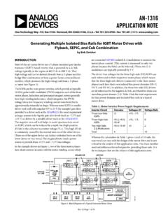
9 InputVoltageFigure16. CompensationRampAmplitudevs. InputVoltageFigure17. MinimumOn-Timevs. TemperaturePWM ComparatorOscillator Sets the RS LatchPWM Comparator resets the RS latchBlank-Out prevents false reset+_VSLTmin (on) Blank-Out time11LM3481, NOVEMBER2007 REVISEDNOVEMBER2014 ProductFolderLinks:LM3481LM3481-Q1 SubmitDocumentationFeedbackCopyright 2007 2014,TexasInstrumentsIncorporated7 LM3481deviceusesa fixedfrequency,PulseWidthModulated(PWM), typicalapplicationcircuit,the peakcurrentthroughthe externalMOSFETis sensedthroughan voltageacrossthis resistoris fed into the ISENpin. This voltageis thenlevelshiftedand fed into thepositiveinputof the outputvoltageis also sensedthroughan externalfeedbackresistordividernetworkan d fed into the erroramplifier(EA)negativeinput(feedback pin, FB).The outputof the erroramplifier(COMPpin) is addedto the slopecompensationrampand fed into the negativeinputof the the startof any switchingcycle,the oscillatorsetsthe RS latchusingthe SET/Blank-outand highsignalon the DR pin (gateof the externalMOSFET)and the externalMOSFET turnson.
10 Whenthe voltageon the positiveinputof the PWMcomparatorexceedsthe negativeinput,the RS latchisresetand the voltagesensedacrossthe senseresistorgenerallycontainsspuriousno isespikes,as shownin forcethe PWMcomparatorto resetthe RS preventthesespikesfromresettingthe latch,a blank-outcircuitinsidethe IC preventsthe PWMcomparatorfromresettingthe latchfor ashortdurationafterthe latchis set. This duration,calledthe blank-outtime,is typically250 ns and is specifiedastmin(on) in loador no-loadconditions,the energydeliveredto the outputcapacitorwhenthe externalMOSFETis on duringthe blank-outtimeis morethanwhatis deliveredto the overvoltagecomparatorinsidethe LM3481preventsthe outputvoltagefromrisingundertheseconditi onsby sensingthe feedback(FBpin) voltageand resettingthe RS latchremainsin a resetstateuntil the outputdecaysto the operatingfrequencydecreasesat light loads,resultingin BasicOperationof the PWMC omparatorFBFA/SYNC/SDCOMPISENAGNDPGNDDRV INS hutdown DetectSYNC/Fixed Frequency detectSoft-start+EA+-+Slope CompensationThermal ReferenceOscillator+220 mVLevel Shifter6+One ShotBias Voltages6 VOvervoltage ComparatorShort-circuitComparatorRamp AdjustV-I ConverterI-V ConverterPWM ComparatorR SQVCCUVLOUVLO40 AVfb + Vovp----12LM3481,LM3481-Q1 SNVS346F NOVEMBER2007.