Transcription of High-Performance Cutting and Grinding Technology …
1 Mitsubishi Heavy Industries Technical Review Vol. 49 No. 3 (September 2012) 3 *1 Process Technology Center, Machine Tool *2 Manager, Process Technology Center, Machine Tool High-Performance Cutting and Grinding Technology for cfrp (Carbon Fiber Reinforced Plastic) HIDEAKI ARISAWA*1 SATORU AKAMA*1 HARUHIKO NIITANI*2 Since it is not only a high-strength, but also light-weight material, carbon fiber reinforced plastic ( cfrp ) has recently been used in certain specific sectors including aircraft, medical equipment and other applications, while attracting attention to the expected future increase in its utilization volume for moderately mass-produced items, such as in the auto industry, as well. This is, however, a difficult-to-machine material which suffers easy delamination of fiber beds.
2 It also shortens tool life and, therefore, studies on tools and Cutting / Grinding technologies are now under way at manufacturers and research facilities. We hereby report our successful materialization of a machining Technology superior to any existing techniques in terms of machining efficiency and tool life. |1. Introduction Carbon fiber reinforced plastic ( cfrp ) is a composite material fabricated by impregnating carbon fibers with resin and then curing and molding it. cfrp , a material boasting high strength and light weight at the same time, started to be practically used first in golf club shafts, fishing rods and other sports goods but in recent years, it has also become more widely used for industrial purposes such as aircraft materials and medical equipment.
3 Of late, cfrp has started to be used extensively in aircraft parts, one of our product categories. It was previously used only in structural portions, such as tail assemblies or floor structural materials, but thanks to the higher reliability brought by such improved materials, it has come to be used for entire structures as in the case of the latest B787 model. There are a number of cfrp manufacturing processes, of which, for aircraft members, an auto-clave process of molding is more frequently used since it promises high strength and stable performance. One of its features is the ability to fabricate large complex-shaped cast parts such as main wing panels and fuselage barrels, thus contributing to weight saving and reduced part counts.
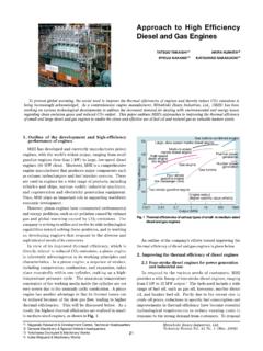
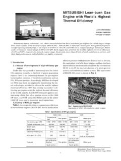
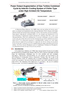
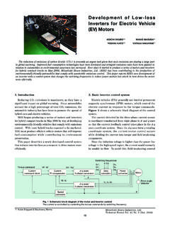
4 On the other hand, feed material, which occurs in excess on the end face at the end of molding, needs to be removed. In addition, fasteners are used to assemble parts with each other and since it is difficult to make holes for such assembling at the time of molding, trimming and drilling become necessary in the post-process (Figure 1). |2. Higher efficiency of trimming Present problems AWJ (abrasive water jet) or an endmill is generally used for cfrp trimming, but the former has problems of limited shapes that can be machined and heavy initial investment/maintenance costs while the latter has difficulty in raising the trimming efficiency due to easy delamination of cfrp fibers, as well as short tool life (Table 1, Figure 2).
5 Mitsubishi Heavy Industries Technical Review Vol. 49 No. 3 (September 2012) 4 Figure 1 Process to manufacture cfrp (Auto-clave molding) Auto-clave molding cures the resin under increasing pressure within the furnace for molding. Since excess feed material occurs at the end of molding, trimming and other finish machining are needed. Table 1 cfrp machining method comparison Advantages Disadvantages AW J Good quality of machined surfaces Limited shapes that can be machined. High cost (of initial investment as well as for maintenance) Endmill Usable with general-purpose equipment Easy delamination Short life of tools Diamond-electroplated tool Usable with general-purpose equipment Long life of tools Narrow chip pockets prevent high feed speed.
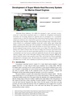
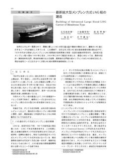
6 Figure 2 Problems with AWJ and endmill machining (a) AWJ is capable of through-machining only and, in addition, requires a catcher to be arranged at the jet end, thus limiting the shapes that can be machined. (b) Endmill trimming easily causes delamination since the Cutting force works in the direction to delaminate fiber beds. Solution As a means to solve this problem, we focused attention on an electroplated tool, the same machining equipment as an endmill. The electroplated tool is a tool on which base metal surface fine diamond abrasives are fixed by electroplating them with nickel. To prevent fiber bed delamination as a problem with endmills, shallow cuts are essential. If an electroplated tool is used, since a large number of diamond abrasives serve as Cutting edges, the cuts per edge can be made shallower than in the case of endmills.
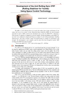
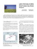
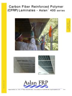
7 Therefore, even if the feed speed is increased for higher-efficiency machining, the occurrence of delamination may be limited. With respect to tool life, an electroplated tool also enjoys higher durability since its Cutting Mitsubishi Heavy Industries Technical Review Vol. 49 No. 3 (September 2012) 5 edge is crystalline diamond, which is worn away more stably than coated and other thin films (Figure 3). Moreover, since machining of cfrp is less subject to loading than metalworking and the abrasive coating hardly flakes off, it seems that an electroplated tool is suitable for cfrp machining. Figure 3 Post- cfrp trimming photo of Cutting edge (abrasive) attrition When trimming cfrp , an endmill suffers chipping at its edge section due to coating delamination while the electroplated tool is subject to stable attrition of its abrasive edge.
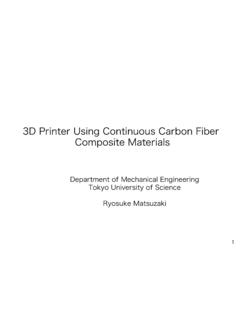
8 Problems with an electroplated tool We conducted experiments on our test electroplated tool and the result was successful trimming without causing any delamination, even at speeds faster than endmill machining. But if the feed rate was increased until it reaches a certain level, sparks came off, thus preventing any more improvement of machining efficiency. We thought that the sparks were caused because the electroplated tool was loaded. Mechanism of loading Let us consider the mechanism of how the tool is loaded before taking measures against loading. The tool is required to have chip pockets spacious enough for the amount of chips derived from trimming but such pockets of ordinary electroplated tools only have an abrasive protrusion size-equivalent of space (Figure 4 (a)).
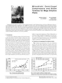
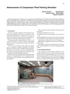
9 Chips from electroplated tool-machined cfrp are in a powdered state, so their volume swells several times from before being machined. For this reason, we thought that the amount of waste chips acceptable by chip pockets was also small, thereby causing the tool to be loaded immediately upon attempting high-efficiency machining. Figure 4 Chip pockets of an electroplated tool (a) A conventional electroplated tool has chip pockets only equivalent in size to an abrasive protrusion and is, therefore, vulnerable to loading. (b) The developed tool has a dimpled surface to ensure enough chip pockets, making loading unlikely. Mitsubishi Heavy Industries Technical Review Vol. 49 No. 3 (September 2012) 6 Measures against loading In order to secure chip pockets spacious enough for our targeted-efficiency trimming on an electroplated tool, we have developed a tool with a dimpled Grinding surface (see Figure 4 (b)).
10 The optimum dimple shape (volume) is closely associated with the aforementioned amount of chips derived and, unless a certain volume or more is secured, loading occurs. It should be noted, however, that if the area of a dimple opening is made too large, the number of working abrasives becomes smaller, adversely affecting the accuracy of finishing and/or tool life. Hence, for the developed tool, a parameter of volume ratio (volume of working chip-pocket sections/amount of chips coming out per revolution of the tool) was established and its relationship with loading was determined by way of work tests. Although the larger the volume ratio, the less likely loading is to occur, where dimples are arranged so as to secure chip pockets, even though the volume ratio is unchanged, if dimples are spaced too far apart, loading occurs to the area distant from the dimple, thus making it difficult for the dimples to have an effect.