Transcription of High Speed Level Shifter Design for Low Power …
1 IOSR Journal of VLSI and Signal Processing (IOSR-JVSP) Volume 6, Issue 2, Ver. I (Mar. -Apr. 2016), PP 73-78 e-ISSN: 2319 4200, p-ISSN No. : 2319 4197 DOI: 73 | Page High Speed Level Shifter Design for Low Power Applications Using 45nm Technology Nisha1, Rajesh Mehra2 1(PG Scholar, Dept. Of ECE , NITTTR Chandigarh , India) 2(Associate Professor, Dept. Of ECE , NITTTR Chandigarh , India) Abstract : As the need of handheld devices such as cell phones, speakers, cameras etc.
2 , is growing, low Power consumption has important Design issues for integrated circuits. Level Shifter is an interfacing circuit which can interface low core voltage to high input- output voltage. In order to achieve reduction in Power consumption and delay, the proposed Level Shifter named Single Supply Level Shifter (SSLS) has been designed .In this paper single supply Level Shifter for low Power high Speed application have been presented and it shows better performance in terms of Power consumption , delay as compared to conventional Level Shifter .
3 All the circuits are simulated at transistor Level using Cadence Virtuoso Tool at 45nm technology with VDD = and T = 270 C. Keywords : CMOS, Delay, Level Shifter , Power consumption, Single supply Level Shifter . I. Introduction The most effective and direct way to reduce Power dissipation in digital LSIs is to reduce their supply voltage because of their quadratic dependence of the Power dissipation on the supply voltage [1]. A Level Shifter is an interfacing circuit which can interface low core voltage to high input- output voltage. Power dissipation in VLSI circuit consists of dynamic and static Power dissipation.
4 Dynamic Power dissipation is mainly due to the charging and discharging of the load capacitor. The static Power is determined by the leakage current through each VLSI circuits can be reduced by scaling supply voltage and capacitance [2]. For any application, understanding the suitability of circuits and selecting the better topology is an important criterion. The conventional Level Shifter compared with single supply Level Shifter using cadence virtuoso tool 45nm technology and schematic will be the Design of both the circuit on the basis of simulation.
5 In this paper, we used cds log window as a schematic editor and simulator to verify the functionality of logic circuits. CADENCE software used for designing the chips and printed circuit boards and gives the analysis of delay, Power consumption , area and other parameters along with Design Rule Check (DRC). Proposed Level Shifter and conventional Level shifters use two voltage supplies, input voltage supply (Vin) and output voltage supply (Vout) [3]. The conventional Level Shifter circuits suffer from the contention between the pull up and pull down transistors which leads to the increase in delay and also the Power consumption because of the DC leakage path from the Power source to ground [4].
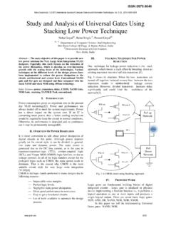
6 The conventional Level shifters have disadvantages of delay variation due to different current driving capabilities of transistors, large Power consumption and failure at low supply core voltage VddL [5]. Figure 1: Block diagram of Level Shifter [5] Basic Level Shifter consists of two pmos transistors MP1 and MP2 act as a cross coupled load, two nmos transistors MN1 and MN2 and two voltages VDDH and VDDL. This paper is organized as follow: Section I gives the introduction of the Level Shifter , Power dissipation in CMOS circuits and overview of single supply Level Shifter .
7 Section II describes the various Level Shifter circuits such as conventional Level Shifter and High Speed Level Shifter Design For Low Power Applications Using 45nm Technology DOI: 74 | Page single supply Level Shifter . After that, Section III presents the experimental results and analysis in terms of Power consumption and propagation delay. The last Section IV concludes the paper followed by the references. II. Level Shifter Circuit Conventional Level Shifter The conventional Level Shifter using cross- coupled PMOS load is shown in Fig.
8 2. Thick gate oxide transistor was used for MN11, MN12, MP11 and MP12 to overcome high voltage stress. The gate source voltage of MN11 and MN12 supply latching voltage on node T1 and T2. This voltage is used for cross-coupled MP11 and MP12 to positive feedback action which result in fully VddH voltage in node T1. When VA is low, MN11 and MP12 are turn on and MN12 and MP11 are turn off. At that time if VA switches to high, following procedure is take place. MN11 off, MN12 on, MP11 on, it results T1 switch low to high and MP12 gets off.
9 Finally the transition time from low voltage to high voltage is decided by the current driving capability of MP11. Pull-down nmos has to overcome the PMOS latch action before the output change state, so the size of MN11 and MN12 are much larger than MP11, MP12 [6]. Figure 2: Conventional Level Shifter [7] The conventional Level Shifter has two disadvantages in actual implementation. First, because of the thick gate oxide transistor s (n11, n12) high threshold voltage, it cannot operate at the core voltage VddL under 1V.
10 Second, current driving capability of n11 and n12 are decided by core voltage VddL, but those of p11 and p12 are controlled by the I/O voltage VddH. So when I/O voltage VddH changes, it will make different current driving capability result in delay variation in Level Shifter . Therefore, it is not adequate for wide range voltage application in a given core voltage [7]. The conventional Level Shifter has large delay because it suffers from contention between the pull-down transistors (MN1 and MN2) and the pull-up transistors (MP1 and MP2).