Transcription of How Digital Engineering Will Change The Way We Work ...
1 How Digital Engineering will Change the way We work Together To Design And Deliver Projects Adam Walmsley, BG&E, Australia. ABSTRACT Our industry is witnessing its biggest Change since CAD was introduced to our workflows. The Digital Engineering process and all it encompasses is shifting the focus from hand sketches, 2D CAD detailing and red pen to an all engrossing and sometimes daunting 3D, 4D and 5D Digital world. This presentation, from the perspective of the design team, will give an insight into how we can benefit from making the 3D model the central collaborative focus point on small bridge projects while also showing how that same model and its intelligent data can be reused by other disciplines, the construction team and the asset owner.
2 As we know, there are increased financial and time pressures on projects in today s climate, forcing our teams to work smaller, smarter and more efficiently together than ever before. The development of an intelligent bridge model can influence design, increase drawing accuracy, reduce human error and identify clashes before site while also including contingency for design changes with minimal rework. INTRODUCTION There is no doubting that Digital Engineering has been the biggest buzz word across the Civil Infrastructure industry for some time now. Our design teams are more frequently required to deliver projects with a BIM deliverable (Building Information Model, more on that later), with many of us not aware of what this entirely means.
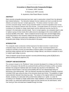
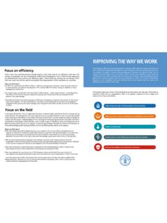
3 As designers in these ever evolving Digital times, we are witnessing the biggest Change since CAD was introduced. The term Digital Engineering encompasses more than simply handing over a BIM at the end of a project, we are able to incorporate Digital processes in all aspects of our roles as bridge designers. This paper will outline how as designers we can benefit from setting our own internal Digital Engineering goals, achieving them and by doing so improving many outcomes for ourselves and other project stakeholders. the way we design, deliver and manage projects is changing with the advancement of technology. There is a statistic that the Construction industry, when it comes to digitisation and investment in digitisation is one of the worst performing sectors, down the bottom of the list with Agriculture and hunting, see figure We have a multitude of current and emerging technologies available to help us work smarter together, there needs to be an increased focus on Digital investment to really see these technologies shape our industry.
4 Digital Engineering as a whole, has the ability to revitalise the way that we would traditionally design, deliver and manage projects across their lifecycle. Figure BODY OF PAPER We have at our fingertips, the ability to utilise current technologies to improve the way our design teams work together. The process around this is known as BIM. BIM stands for Building Information Modelling. In short, Building refers to anything that we can construct. Information refers to the data that we can input into the project and Modelling refers to the way that all the project data is managed and contained - inside an accurate Digital 3D model that represents the exact dimensions of the proposed built asset.
5 Worth noting, the I is one of the most important factors that supports and drives BIM as a whole. The data and information that we can input in the model plays a crucial role in the overall usefulness of the model. BIM is a process and for the project owner, asset manager, designers and construction teams to really see the benefits of adopting this process on a project all of these stakeholders must be on board. In Australia, we are seeing a gradual Change and increased adoption of BIM however it may be some time before we can confidently say we are delivering complete BIM projects. As designers, we can see the benefits of adopting internal BIM processes by setting and ultimately achieving our own Digital Engineering goals.
6 Technology plays a great role in doing this, although it is not the only driver. A Change in mindset is required across the board to think Digital . This paper will show how as a team of bridge designers we can work smarter and more efficiently by sharing Digital design data across different software platforms, using this data to update the Digital single point of truth model which results in more detailed information, accurate drawings, ultimately resulting in time saved and less errors. At BG&E Autodesk Revit is our software of choice when it comes to being the single point of truth model. People will tell you that Revit cannot do certain things, especially with bridges, but with some technical knowhow it is a great tool.
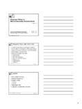
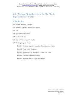
7 The Revit model can be thought of as one big database containing information about the bridge. Data about individual bridge elements can be easily associated to the modelled elements (see Figure ), scheduled, quantified and manipulated to present us with detailed information. The data can be sent to other design software for analysis, brought back in and updated in the model accordingly. The non-Revit users in our team are able to use software to view the model, check its geometries, validate the data and communicate any necessary design changes without having to see a drawing. This process requires our team to Change the way they work , to focus our attention on the 3D model as the central point of communication, which can be a challenge in itself however we have seen the results in our team when we implement these processes successfully.
8 Traditional workflows would see a range of project information scattered across hand sketches, project servers, reports and email inboxes. Bringing all of the project information into a centralised location improves the communication flow and with the introduction of cloud technologies this has also allowed our team to work just as effectively from remote locations or other offices. Figure Bridge bearing data contained inside the model. A simple example shown below is our process for the design of Piles. Our piles are modelled under the abutments and piers, a unique mark is associated to each pile, AA-01, AA-02 etc. Schedules with empty fields of data are generated inside of Revit and can be placed on a sheet awaiting the input from someone else.
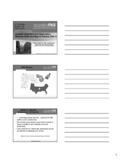
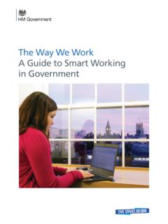
9 We can then export the pile information to excel and send it to our designer. The designer can now populate all of the design data in excel, including pile lengths, diameters, reinforcement, loadings, the list goes on. Once complete we can import this data back into Revit and all of our piles, their sizes, and the schedule is updated automatically. It is clear how we are minimising risk of manual data-entry errors, saving time because it s quicker than the designer hand marking a schedule and we are also saving some trees with the reduction of paper. As the design progresses and further changes are required the excel spreadsheet can simply be updated as necessary. This process can easily be replicated across other elements in the bridge including bearings and girders.
10 Figure Sharing design data across different software platforms. Another example is how we can use the model to automatically generate setout points for our deck, based on the 3D road alignment. Traditionally this process would be done with a series of calculations or in an excel spreadsheet and data transferred to the drawings. Things tend to get interesting when you introduce more complex geometries and sometimes the spreadsheets can be incorrect. This process alleviates the risk and time spent rectifying changes if errors are found. We can take our 3D modelled deck in Revit, use an add-on to Revit called Dynamo Studio, analyse the perimeter of the deck to get the Easting, Northing and RL data at various cross sections, perpendicular to the control line.