Transcription of How Spark Transmitters Work
1 How Spark Transmitters work by Hal Kennedy, N4GG 1 [This article was written in support of The History of QST, Volume 1 Technology published by the ARRL and available at ] Pondering Spark transmitter operation is, at best, an infrequent occurrence among today s amateurs. It shouldn t be however, because in addition to the historical significance of our original methods, virtually all of us own and operate one or more Spark rigs today. If you drive a gasoline-powered car - or even if you don t - you have listened to the ignition noise from one. What is that noise? It is the broad spectrum electromagnetic (EM) wave propagation from a Spark gap. Every time a Spark plug fires, that electrical impulse excites the ignition wiring in the vehicle an antenna which radiates an EM wave; sometimes with considerable power, to considerable distance and over a very broad range of frequencies.
2 A modern car uses the exact components found in a 1900 Spark transmitter ; a battery, an induction coil to step up to high voltage (ignition coil), a Spark gap ( Spark plug) and an antenna (ignition wiring). All that s missing is a telegraph key. If we grounded the car s chassis, connected an antenna directly to the ignition coil s HV output and added a telegraph key in series with the ignition coil primary, we would have a complete 1900 Spark gap transmitter along with 21st century comfort features like a leather operating seat and a sun roof. What could we do with this lash-up? We could transmit Morse code to a range of about 10 miles, with the emission occupying a huge amount of spectrum, centered on a frequency determined by the L-C resonance of the antenna s series inductance and parallel capacitance to ground.
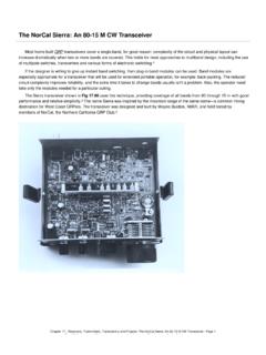
3 We would also endure the wrath of the FCC and anyone operating a receiver for miles around. Amateur Spark had left the air by 1923 and was outlawed in 1929 for good reason. A pictorial diagram of a 1900 Spark transmitter is shown in Figure 1. The basic components include a battery supply, key, induction coil (HV transformer), Spark gap and connections to an antenna and ground. Also shown is an inductor in series with the antenna to provide for small adjustments, and an interrupter to chop the DC battery voltage into a quasi-AC waveform to allow the induction coil to operate as a transformer. Figure 1. Diagram of a 1900 Spark gap transmitter Basic operation is straightforward. Close the key and the induction coil s output rises to a sufficient voltage to begin and then maintain an arc across the Spark gap.
4 But how does this create an EM wave we can transmit? The Spark gap itself is an electronic switch. When not firing, it is an open circuit. When firing or arcing over the air within the gap is ionized into a conducting plasma and the resistance across the gap drops to around two ohms. Gaps require high voltage to begin firing, but require current, not voltage, to maintain firing once started. Spark gap induction coils used limiting mechanisms to continue to deliver small amount of current to the gap, (a 2 near-short across their secondary) without burning up. The structure of the ionized discharge across the gap is highly erratic, with constant current fluctuations occurring within plasma. These fluctuations occur rapidly, with a frequency content that covers nearly the entire EM spectrum.
5 In 1887 Heinrich Hertz referred to a Spark gap as an oscillator. Being connected directly to the antenna, the broad spectrum current fluctuations at the Spark gap are radiated by the antenna. Note that with the gap firing, its 2 resistance completes an RF path from the antenna back to ground, allowing current to flow in the antenna. How Spark Transmitters work by Hal Kennedy, N4GG How Spark Transmitters work by Hal Kennedy, N4GG 2 Spark gaps in the earliest Transmitters fired continuously as long as the key was depressed. This produced an output signal that sounded like a buzz or a sizzle in a receiver. This was very inefficient as continuous firing of the gap caused the power in the Spark to be limited by the current the induction coil could deliver into the 2 load of the gap typically 100 mA or less.
6 In addition to poor efficiency, a 1900 Spark rig had other unfortunate characteristics. Opening the gap too wide as well as other disturbances could cause misfiring, placing the 10,000 volts at the secondary of a typical induction coil directly on the antenna. This made for potentially lethal accidents. Also, the antenna radiation resistance in series with ohmic and ground resistance yielded low Q and furthered the broadband nature of the EM radiation. You can hear a car s ignition noise from below 30 kHz to above 30 MHz, about the same as a 1900 Spark rig. Spreading the emitted energy across that much spectrum drastically reduces the output power on any single frequency. These characteristics limited early Spark transmission to a range of about 10 miles.
7 The inability to control bandwidth of both Transmitters and receivers in 1900 also meant that within a 10 mile radius it only took two Transmitters operating at the same time to produce intractable QRM. However, amateurs are an inventive bunch, and from 1900 to 1915 that was in full evidence. In that era, experimentation was the order of the day, and Spark Transmitters quickly underwent major improvements based on empirical trial and error. The first advance was adding a capacitor across the induction coil secondary. The capacitor eliminated continuous arcing at the gap. Instead, the capacitor charged until sufficient voltage was achieved to fire the gap, at which point the gap fired, the capacitor was discharged and the Spark extinguished.
8 The energy stored in the capacitor and delivered to the gap was CV2. At 10,000 volts, voltage squared yields a lot of energy! The gap current was no longer determined by the induction coil trying to drive 2 , it was determined by the energy stored in the capacitor. As a result, gap current increased orders of magnitude while the transmitter input power remained unchanged. The simple addition of the capacitor provided two major improvements. The gap current and corresponding antenna current went up, and the quick discharge of the capacitor removed the 2 resistance from the antenna circuit between firings. This fundamentally altered the excitation of the antenna from being continuously excited by a wide-band low current oscillator, to being excited by impulses from a high current gap discharge.
9 When the gap was not firing, the antenna no longer had a 2 connection to ground and was free to ring at its own natural resonant frequency. The introduction of the HV capacitor across the gap greatly increased output power and narrowed radiated bandwidth. Both improved efficiency. Spark transmitter output had moved from low power, white noise to higher power, narrow band quasi sine waves. This modification alone pushed Spark transmission well beyond 10 miles. It also left both amateurs and commercial interests such as those of Marconi with the idea that from here forward more powerful sparks and higher antennas were all that was needed to extend range. This viewpoint persists today and when viewed in the long term is just as incorrect now as it was then.
10 The major performance enhancements in amateur and commercial transmission have been technology driven. Moving from Spark to CW and from AM to SSB have had far greater impacts than increased power and higher antennas. Meanwhile, power and antenna height can t be discounted. By 1905, the addition of a HV capacitor and an output tuning coil to further reduce bandwidth, together with raising power and antenna height, resulted in the night-time ranges shown in Table 1. Coil length determines the voltage across the capacitor at the gap. There were no regulations you could run as much power as you could generate. Table 1. 1905 Spark transmitter performance as a function of power and antenna height. Coil Length (inches) Antenna Height (feet) Distance (miles) 1 40.