Transcription of HR2000+ Data Sheet - oceanoptics.com
1 294-00000-000-05-201604 1 hr2000 + data Sheet Description The Ocean Optics hr2000 + Spectrometer includes the linear CCD-array optical bench, plus all the circuits necessary for spectrometer operation. The result is a compact, flexible system, with no moving parts, that's easily integrated as an OEM component. The hr2000 + spectrometer is a unique combination of technologies providing users with both an unusually high spectral response and high optical resolution in a small footprint. The electronics have been designed for considerable flexibility in connecting to various modules as well as external interfaces. The hr2000 + interfaces to PCs, PLCs and other embedded controllers through USB or RS-232 communications. The information included in this data Sheet provides detailed instructions on the connection and operation of the hr2000 +.
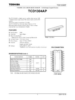
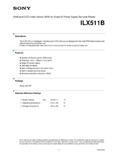
2 The detector used in the hr2000 + spectrometer is a high-sensitivity 2048-element CCD array from Sony, product number ILX511B. (For complete details on this detector, visit Sony s web site at Ocean Optics applies a coating to all ILX511 detectors, so the optical sensitivity could vary from that specified in the Sony datasheet). The hr2000 + operates from the +5V power, provided through the USB, or from a separate power supply and either a USB or RS-232 interface. The hr2000 + is a microcontroller-controlled spectrometer, thus all operating parameters are implemented through software interfacing to the unit. hr2000 + data Sheet 2 294-00000-000-05-201604 The HR4000 Breakout Box (HR4-BREAKOUT) is available from Ocean Optics for use with the hr2000 + Spectrometer.
3 The HR4000 Breakout Box is a passive module that separates the signals from their 30-pin port to an array of standard features found on the hr2000 + Spectrometer. Features An optical resolution of ~ to nm (FWHM) A wide variety of optics available 14 gratings 6 slit widths 6 optical filters, 1 order-sorting filter Electrical Performance 14 bit, 5 MHz A/D Converter Integration times from 1 ms to 65 s 4 or 5 triggering modes (depending on firmware) Embedded microcontroller allows programmatic control of all operating parameters and Standalone operation USB 480 Mbps (High-speed) & 12 Mbps (Full speed) RS232 115 Kbaud Communication Standard for digital accessories (I2C) Onboard Pulse Generator 2 programmable strobe signals for triggering other devices Software control of nearly all pulse parameters Onboard GPIO 10 user programmable digital I/O Onboard Analog Interface Analog Input: 13bit, 0-5V Analog Output.
4 9bit, 0-5V EEPROM storage for Wavelength Calibration Coefficients Linearity Correction Coefficients Absolute Irradiance Calibration (optional) Plug-n-Play Interface for PC applications 30-pin connector for interfacing to external products CE Certification hr2000 + data Sheet 294-00000-000-05-201604 3 Specifications Specifications Criteria Absolute Maximum Ratings: VCC Voltage on any pin + VDC Vcc Physical Specifications: Physical Dimensions Weight mm x mm x mm 570 g Power: Power requirement (master) Supply voltage Power-up time 220 mA at +5 VDC V ~5s depending on code size Spectrometer: Design Focal length (input and output) Input Fiber Connector Gratings Entrance Slit Detector Filters Asymmetric crossed Czerny-Turner F/4, 101 mm SMA 905 to single-strand optical fiber ( NA) 14 different gratings 5, 10, 25, 50, 100, or 200 m slits.
5 (Slits are optional. In the absence of a slit, the fiber acts as the entrance slit.) Sony ILX511B CCD 2nd & 3rd order rejection, long pass (optional) Spectroscopic: Integration Time Dynamic Range Signal-to-Noise Readout Noise (single dark spectrum) Resolution Spectrometer Channels 1millisecond 65 seconds 2 x 10⁸ (system), 1300:1 (single acquisition) 250:1 (single acquisition) 12 counts RMS, 20 counts peak-to-peak ~ to nm (FWHM), varies by configuration (see for configuration options) One Environmental Conditions: Temperature Humidity -30 to +70 C Storage & -10 to +50 C Operation 0% - 90% non-condensing Interfaces: USB RS-232 I2C USB , 480 Mbps 2-wire RS-232 Inter-Integrated Circuit 2-Wire serial BUS hr2000 + data Sheet 4 294-00000-000-05-201604 Mechanical Diagram Figure 1.
6 hr2000 + Outer Dimensions hr2000 + data Sheet 294-00000-000-05-201604 5 Electrical Pinout Listed below is the pin description for the hr2000 + Accessory Connector (J3) located on the front vertical wall of the unit. The connector is a Pak50TM model from 3M Corp. Headed Connector Part# P50-030P1-RR1-TG. It mates with Part # P50-030S-EA (requires two: (50 mil) flat ribbon cable: Recommended 3M 3365 Series). Pin# Description Alt Function 1 RS232 Rx 2 RS232 Tx 3 GPIO(2) Reserved 4 V5_SW 5 Ground 6 I2C SCL 7 GPIO(0) Reserved 8 I2C SDA 9 GPIO(1) Reserved 10 External Trigger In 11 GPIO(3) Reserved 12 VCC, VUSB or 5 Vin 13 Reserved 14 VCC, VUSB or 5 Vin 15 Reserved 16 GPIO(4) Reserved 17 Single Strobe 18 GPIO(5) Reserved 19 Reserved 20 Continuous Strobe 21 SPI Chip Select 22 GPIO(6) Reserved 23 Analog In (0-5V) For future use 24 Analog Out (0-5V) 25 Lamp Enable 26 GPIO(7) Reserved 27 Ground 28 GPIO(8) Reserved 29 Ground 30 GPIO(9)
7 Reserved Pin Orientation USB Port Looking at Front of hr2000 + 2 4 6 8 10 12 14 16 18 20 22 24 26 28 30 1 3 5 7 9 11 13 15 17 19 21 23 25 27 29 hr2000 + data Sheet 6 294-00000-000-05-201604 Pin Definition and Descriptions Pin # Function Input/Output Description 1 RS232 Tx Output RS232 Transmit signal for communication with PC connect to DB9 pin 2 2 RS232 Rx Input RS232 Receive signal for communication with PC connect to DB9 pin 3 3 GPIO (2) Input/Output General purpose, software-programmable digital input/output (channel number) 4 V5_SW Output This is a regulated 5-Volt power pin out of the hr2000 +. It can supply 50mA (max). 5 Ground Input/Output Ground 6 I2C SCL Input/Output The I2C Clock signal for communications to other I2C peripherals 7 GPIO (0) Input/Output General purpose, software-programmable digital input/output (channel number) 8 I2C SDA Input/Output The I2C data signal for communications to other I2C peripherals 9 GPIO (1) Input/Output General purpose, software-programmable digital input/output (channel number) 10 External Trigger In Input The TTL input trigger signal.
8 In External Hardware Trigger mode this is a rising edge trigger input. In Software Trigger Mode this is an Active HIGH Level signal. In External Synchronization Mode (or External Hardware Level Trigger Mode) this is a clock input, which defines the integration period of the spectrometer. 11 GPIO (3) Input/Output General purpose, software-programmable digital input/output (channel number) 12 VCC , VUSB or 5 Vin Input or Output This is the input power pin to the hr2000 +. Additionally when operating via a Universal Serial Bus (USB) this is the USB power connection (+5V) which can be used to power other peripherals (Care must be taken to insure that the peripheral complies with USB Specifications). 13 Reserved Output 14 VCC , VUSB or 5 Vin Input or Output This is the input power pin to the hr2000 +. Additionally when operating via a Universal Serial Bus (USB) this is the USB power connection (+5V) which can be used to power other peripherals (Care must be taken to insure that the peripheral complies with USB Specifications).
9 15 Reserved Input 16 GPIO (4) Input/Output General purpose, software-programmable digital input/output (channel number) 17 Single Strobe Output TTL output pulse used as a strobe signal, which has a programmable delay relative to the beginning of the spectrometer integration period. 18 GPIO (5) Input/Output General purpose, software-programmable digital input/output (channel number) hr2000 + data Sheet 294-00000-000-05-201604 7 Pin Definition and Descriptions (Cont d) Pin # Function Input/Output Description 19 Reserved Output 20 Continuous Strobe Output TTL output signal used to pulse a strobe that is divided down from the Master Clock signal 21 Reserved Output 22 GPIO (6) Input/Output General purpose, software-programmable digital input/output (channel number) 23 Reserved Input 24 Analog Out (0-5V) Output The Analog Out is a 9-bit programmable output voltage with a 0-5 Volt range.
10 25 Lamp Enable Output A TTL signal that is driven Active HIGH when the Lamp Enable command is sent to the spectrometer 26 GPIO (7) Input/Output General purpose, software-programmable digital input/output (channel number) 27 Ground Input/Output Ground 28 GPIO (8) Input/Output General purpose, software-programmable digital input/output (channel number) 29 Ground Input/Output Ground 30 GPIO (9) Input/Output General purpose, software-programmable digital input/output (channel number) hr2000 + data Sheet 8 294-00000-000-05-201604 Internal Operation Pixel Definition A series of pixels in the beginning of the scan have been covered with an opaque material to compensate for thermal induced drift of the baseline signal. As the hr2000 + warms up, the baseline signal will shift slowly downward a few counts depending on the external environment.