Transcription of TOSHIBA CCD LINEAR IMAGE SENSOR CCD(Charge …
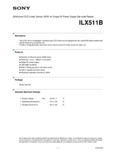
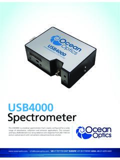
1 tcd1304ap 2001-10-15 1 TOSHIBA CCD LINEAR IMAGE SENSOR CCD(Charge coupled Device) tcd1304ap The tcd1304ap is a high sensitive and low dark current 3648 elements LINEAR IMAGE SENSOR . The SENSOR can be used for POS scanner. The device consist of sensitivity CCD chip. The tcd1304ap has electronic shutter function (ICG). Electronic shutter funtion can keep always output voltage constant that vary with intensity of lights. FEATURES l Pixel Number : 3648 l Pixel Size : 8 m 200 m l Photo Sensing Region : High Sensitive & Low Dark Current pn Photodiode l Internal Circuit : CCD Drive Circuit l Power Supply : Only Drive (MIN.) l Function : Electronic Shutter Sample and Hold Circuit l Package : 22 Pin DIP (T CAPP) TOSHIBA CCD ADVANCED PLASTIC PACKAGE MAXIMUM RATINGS (Note 1) CHARACTERISTIC SYMBOL RATING UNIT Master Clock Pulse Voltage V M SH Pulse Voltage VSH ICG Pulse Voltage VICG Digital Power Supply VDD Analog Power Supply VAD ~7 V Operating Temperature Topr 25~60 C Storage Temperature Tstg 40~100 C Note: All voltage are with respect to SS terminals.
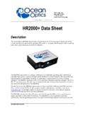
2 (Ground) Weight: (Typ.) PIN CONNECTION (TOP VIEW) tcd1304ap 2001-10-15 2 CIRCUIT DIAGRAM PIN NAMES M Master Clock SH Shift Gate ICG Integration Clear Gate VAD Power (Analog) VDD Power (Digital) SS Ground NC Non Connection tcd1304ap 2001-10-15 3 OPTICAL / ELECTRICAL CHARACTERISTICS (Ta = 25 C, V = (PULSE), f = , tINT (INTEGRATION TIME) = 10ms, LOAD RESISTANCE = 100k , VAD = VDD = , LIGHT SOURCE = DAYLIGHT FLUORESCENT LAMP) CHARACTERISTIC SYMBOL UNIT NOTE Sensitivity R 110160 V / lx s Photo Response Non Uniformity PRNU 10 % (Note 2)Register Imbalance RI 3 % (Note 3)Saturation Output Voltage VSAT 450600 mV VOD= (Note 4)Dark Signal Voltage VMDK 2 5 mV (Note 5)
3 Total Transfer Effeiciency TTE 92 95 % Dynamic Range DR 300 (Note 6)Saturation Exposure SE lx s (Note 7)DC Power Dissipation PD 25 75 mW DC Signal Output Voltage VOS V (Note 8)Output Impedance Zo k IMAGE Lag of Electronic Shutter VLAGICG 10 mV Tint=100 sNote 2: Measured at 50% of SE (Typ.) Definition of PRNU: PRNU = ()%100 ccD Where c is average of total signal outputs andcDis the maximum deviation from c under uniform illumination. Note 3: Measured at 50% of SE (Typ.) RI is defined as follows: RI = ()%100 364736471n1nn c =+c-c Where c n and c n+1 are signal outputs of each average of total signal outputs.
4 Note 4: VSAT is defined as minimum saturation output voltage of all effective pixels. Note 5: VMDK is defined as maximum dark signal voltage of all effective pixels. tcd1304ap 2001-10-15 4 Note 6: Definition of DR : DR = MDKVSATV VMDK is proportional to tINT (Integration time). So the shorter tINT condition makes wider DR value. Note 7: Definition of SE : SE = ()s lxRSATV Note 8: DC signal output voltage is defined as follows: . tcd1304ap 2001-10-15 5 OPERATING CONDITION CHARACTERISTIC SYMBOL MIN TYP. MAX UNIT H Level Master Clock Pulse Voltage L Level V M 0 0 V H Level SH Pulse Voltage L Level VSH 0 0 V H Level ICG Pulse Voltage L Level VICG 0 0 V Digital Power Supply VDD V Analog Power Supply VAD V Note: VAD = VDD MAX.
5 Voltage of Pulse Voltage H Level = VDD MIN. Voltage of Pulse Voltage H Level = VDD CLOCK CHARACTERISTICS (Ta = 25 C) (VAD = VDD ) CHARACTERISTIC SYMBOL MIN TYP. MAX UNITM aster Clock Frequency f M 2 4 MHzData Rate fDATA 1 MHzMaster Clock Capacitance C M 10 pF Shift Pulse Capacitance CSH 600 pF ICG Pulse Capacitance CICG 250 pF CLOCK CHARACTERISTICS (Ta = 25 C) ( >VAD = VDD ) CHARACTERISTIC SYMBOL MIN TYP.
6 MAX UNITM aster Clock Frequency f M 2 MHzData Rate fDATA MHz tcd1304ap 2001-10-15 6 TIMING CHART tcd1304ap 6 tcd1304ap 2001-10-15 7 tcd1304ap 7 TIMING CHART (Use electric shutter function) tcd1304ap 2001-10-15 8 TIMING REQUIREMENTS CHARACTERISTIC SYMBOL MIN TYP. MAX UNITICG Pulse DELAY t1 1000 5000 ns Pulse Timing of ICG and S H t2 100 500 1000 ns SH Pulse Width t3 1000 ns Pulse Timing of ICG and M t4 0 20 * ns *: You keep M High Level.
7 Note: If you use electronic shutter function. tINT (MIN.) = 10 s tcd1304ap 2001-10-15 9 USE ELECTRONIC SHUTTER Pulse Timing of SH and ICG SH cycle = Tint tINT (MIN.) = 10 s You have always same SH pulse width (t3). tcd1304ap 2001-10-15 10 TYPICAL PERFOMANCE CURVES tcd1304ap 2001-10-15 11 TYPICAL PERFOMANCE CURVES tcd1304ap 2001-10-15 12 TYPICAL DRIVE CIRCUIT tcd1304ap 2001-10-15 13 CAUTION 1. Window Glass The dust and stain on the glass window of the package degrade optical performance of CCD SENSOR . Keep the glass window clean by saturating a cotton swab in alcohol and lightly wiping the surface, and allow the glass to dry, by blowing with filtered dry N2. Care should be taken to avoid mechanical or thermal shock because the glass window is easily to damage. 2. Electrostatic Breakdown Store in shorting clip or in conductive foam to avoid electrostatic breakdown.
8 CCD IMAGE SENSOR is protected against static electricity, but interior puncture mode device due to static electricity is sometimes detected. In handing the device, it is necessary to execute the following static electricity preventive measures, in order to prevent the trouble rate increase of the manufacturing system due to static electricity. a. Prevent the generation of static electricity due to friction by making the work with bare hands or by putting on cotton gloves and non-charging working clothes. b. Discharge the static electricity by providing earth plate or earth wire on the floor, door or stand of the work room. c. Ground the tools such as soldering iron, radio cutting pliers of or pincer. It is not necessarily required to execute all precaution items for static electricity. It is all right to mitigate the precautions by confirming that the trouble rate within the prescribed range.
9 3. Incident Light CCD SENSOR is sensitive to infrared light. Note that infrared light component degrades resolution and PRNU of CCD SENSOR . 4. Lead Frame Forming Since this package is not strong against mechanical stress, you should not reform the lead frame. We recommend to use a IC-inserter when you assemble to PCB. 5. Soldering Soldering by the solder flow method cannot be guaranteed because this method may have deleterious effects on prevention of window glass soiling and heat resistance. Using a soldering iron, complete soldering within ten seconds for lead temperatures of up to 260 C, or within three seconds for lead temperatures of up to 350 C. tcd1304ap 2001-10-15 14 PACKAGE DIMENSIONS Note 1: No. 1 SENSOR ELEMENT (S1) TO EDGE OF PACKAGE. Note 2: TOP OF CHIP TO BOTTOM OF PACKAGE. Note 3: GLASS THICKNES (n = ) Weight: (Typ.)
10 Unit : mm tcd1304ap 2001-10-15 15 TOSHIBA is continually working to improve the quality and reliability of its products. Nevertheless, semiconductor devices in general can malfunction or fail due to their inherent electrical sensitivity and vulnerability to physical stress. It is the responsibility of the buyer, when utilizing TOSHIBA products, to comply with the standards of safety in making a safe design for the entire system, and to avoid situations in which a malfunction or failure of such TOSHIBA products could cause loss of human life, bodily injury or damage to property. In developing your designs, please ensure that TOSHIBA products are used within specified operating ranges as set forth in the most recent TOSHIBA products specifications. Also, please keep in mind the precautions and conditions set forth in the Handling Guide for Semiconductor devices , or TOSHIBA Semiconductor Reliability Handbook The TOSHIBA products listed in this document are intended for usage in general electronics applications (computer, personal equipment, office equipment, measuring equipment, industrial robotics, domestic appliances, etc.)