Transcription of HR2000+ Data Sheet - oceanoptics.com
1 294-00000-000-05-201604 1 hr2000 + data Sheet Description The ocean optics hr2000 + Spectrometer includes the linear CCD-array optical bench, plus all the circuits necessary for spectrometer operation. The result is a compact, flexible system, with no moving parts, that's easily integrated as an OEM component. The hr2000 + spectrometer is a unique combination of technologies providing users with both an unusually high spectral response and high optical resolution in a small footprint. The electronics have been designed for considerable flexibility in connecting to various modules as well as external interfaces. The hr2000 + interfaces to PCs, PLCs and other embedded controllers through USB or RS-232 communications.
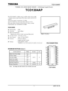
2 The information included in this data Sheet provides detailed instructions on the connection and operation of the hr2000 +. The detector used in the hr2000 + spectrometer is a high-sensitivity 2048-element CCD array from Sony, product number ILX511B. (For complete details on this detector, visit Sony s web site at ocean optics applies a coating to all ILX511 detectors, so the optical sensitivity could vary from that specified in the Sony datasheet). The hr2000 + operates from the +5V power, provided through the USB, or from a separate power supply and either a USB or RS-232 interface. The hr2000 + is a microcontroller-controlled spectrometer, thus all operating parameters are implemented through software interfacing to the unit. hr2000 + data Sheet 2 294-00000-000-05-201604 The HR4000 Breakout Box (HR4-BREAKOUT) is available from ocean optics for use with the hr2000 + Spectrometer.
3 The HR4000 Breakout Box is a passive module that separates the signals from their 30-pin port to an array of standard features found on the hr2000 + Spectrometer. Features An optical resolution of ~ to nm (FWHM) A wide variety of optics available 14 gratings 6 slit widths 6 optical filters, 1 order-sorting filter Electrical Performance 14 bit, 5 MHz A/D Converter Integration times from 1 ms to 65 s 4 or 5 triggering modes (depending on firmware) Embedded microcontroller allows programmatic control of all operating parameters and Standalone operation USB 480 Mbps (High-speed) & 12 Mbps (Full speed) RS232 115 Kbaud Communication Standard for digital accessories (I2C) Onboard Pulse Generator 2 programmable strobe signals for triggering other devices Software control of nearly all pulse parameters Onboard GPIO 10 user programmable digital I/O Onboard Analog Interface Analog Input: 13bit, 0-5V Analog Output: 9bit, 0-5V EEPROM storage for Wavelength Calibration Coefficients Linearity Correction Coefficients Absolute Irradiance Calibration (optional) Plug-n-Play Interface for PC applications 30-pin connector for interfacing to external products CE Certification hr2000 + data Sheet 294-00000-000-05-201604 3 Specifications Specifications Criteria Absolute Maximum Ratings.
4 VCC Voltage on any pin + VDC Vcc Physical Specifications: Physical Dimensions Weight mm x mm x mm 570 g Power: Power requirement (master) Supply voltage Power-up time 220 mA at +5 VDC V ~5s depending on code size Spectrometer: Design Focal length (input and output) Input Fiber Connector Gratings Entrance Slit Detector Filters Asymmetric crossed Czerny-Turner F/4, 101 mm SMA 905 to single-strand optical fiber ( NA) 14 different gratings 5, 10, 25, 50, 100, or 200 m slits. (Slits are optional. In the absence of a slit, the fiber acts as the entrance slit.) Sony ILX511B CCD 2nd & 3rd order rejection, long pass (optional) Spectroscopic: Integration Time Dynamic Range Signal-to-Noise Readout Noise (single dark spectrum) Resolution Spectrometer Channels 1millisecond 65 seconds 2 x 10⁸ (system), 1300:1 (single acquisition) 250:1 (single acquisition) 12 counts RMS, 20 counts peak-to-peak ~ to nm (FWHM), varies by configuration (see for configuration options) One Environmental Conditions: Temperature Humidity -30 to +70 C Storage & -10 to +50 C Operation 0% - 90% non-condensing Interfaces.
5 USB RS-232 I2C USB , 480 Mbps 2-wire RS-232 Inter-Integrated Circuit 2-Wire serial BUS hr2000 + data Sheet 4 294-00000-000-05-201604 Mechanical Diagram Figure 1. hr2000 + Outer Dimensions hr2000 + data Sheet 294-00000-000-05-201604 5 Electrical Pinout Listed below is the pin description for the hr2000 + Accessory Connector (J3) located on the front vertical wall of the unit. The connector is a Pak50TM model from 3M Corp. Headed Connector Part# P50-030P1-RR1-TG. It mates with Part # P50-030S-EA (requires two: (50 mil) flat ribbon cable: Recommended 3M 3365 Series).
6 Pin# Description Alt Function 1 RS232 Rx 2 RS232 Tx 3 GPIO(2) Reserved 4 V5_SW 5 Ground 6 I2C SCL 7 GPIO(0) Reserved 8 I2C SDA 9 GPIO(1) Reserved 10 External Trigger In 11 GPIO(3) Reserved 12 VCC, VUSB or 5 Vin 13 Reserved 14 VCC, VUSB or 5 Vin 15 Reserved 16 GPIO(4) Reserved 17 Single Strobe 18 GPIO(5) Reserved 19 Reserved 20 Continuous Strobe 21 SPI Chip Select 22 GPIO(6) Reserved 23 Analog In (0-5V) For future use 24 Analog Out (0-5V) 25 Lamp Enable 26 GPIO(7) Reserved 27 Ground 28 GPIO(8) Reserved 29 Ground 30 GPIO(9) Reserved Pin Orientation USB Port Looking at Front of hr2000 + 2 4 6 8 10 12 14 16 18 20 22 24 26 28 30 1 3 5 7 9 11 13 15 17 19 21 23 25 27 29 hr2000 + data Sheet 6 294-00000-000-05-201604 Pin Definition and Descriptions Pin # Function Input/Output Description 1 RS232 Tx Output RS232 Transmit signal for communication with PC connect to DB9 pin 2 2 RS232 Rx Input RS232 Receive signal for communication with PC connect to DB9 pin 3 3 GPIO (2) Input/Output General purpose, software-programmable digital input/output (channel number)
7 4 V5_SW Output This is a regulated 5-Volt power pin out of the hr2000 +. It can supply 50mA (max). 5 Ground Input/Output Ground 6 I2C SCL Input/Output The I2C Clock signal for communications to other I2C peripherals 7 GPIO (0) Input/Output General purpose, software-programmable digital input/output (channel number) 8 I2C SDA Input/Output The I2C data signal for communications to other I2C peripherals 9 GPIO (1) Input/Output General purpose, software-programmable digital input/output (channel number) 10 External Trigger In Input The TTL input trigger signal. In External Hardware Trigger mode this is a rising edge trigger input. In Software Trigger Mode this is an Active HIGH Level signal. In External Synchronization Mode (or External Hardware Level Trigger Mode) this is a clock input, which defines the integration period of the spectrometer.
8 11 GPIO (3) Input/Output General purpose, software-programmable digital input/output (channel number) 12 VCC , VUSB or 5 Vin Input or Output This is the input power pin to the hr2000 +. Additionally when operating via a Universal Serial Bus (USB) this is the USB power connection (+5V) which can be used to power other peripherals (Care must be taken to insure that the peripheral complies with USB Specifications). 13 Reserved Output 14 VCC , VUSB or 5 Vin Input or Output This is the input power pin to the hr2000 +. Additionally when operating via a Universal Serial Bus (USB) this is the USB power connection (+5V) which can be used to power other peripherals (Care must be taken to insure that the peripheral complies with USB Specifications). 15 Reserved Input 16 GPIO (4) Input/Output General purpose, software-programmable digital input/output (channel number) 17 Single Strobe Output TTL output pulse used as a strobe signal, which has a programmable delay relative to the beginning of the spectrometer integration period.
9 18 GPIO (5) Input/Output General purpose, software-programmable digital input/output (channel number) hr2000 + data Sheet 294-00000-000-05-201604 7 Pin Definition and Descriptions (Cont d) Pin # Function Input/Output Description 19 Reserved Output 20 Continuous Strobe Output TTL output signal used to pulse a strobe that is divided down from the Master Clock signal 21 Reserved Output 22 GPIO (6) Input/Output General purpose, software-programmable digital input/output (channel number) 23 Reserved Input 24 Analog Out (0-5V) Output The Analog Out is a 9-bit programmable output voltage with a 0-5 Volt range. 25 Lamp Enable Output A TTL signal that is driven Active HIGH when the Lamp Enable command is sent to the spectrometer 26 GPIO (7) Input/Output General purpose, software-programmable digital input/output (channel number) 27 Ground Input/Output Ground 28 GPIO (8) Input/Output General purpose, software-programmable digital input/output (channel number) 29 Ground Input/Output Ground 30 GPIO (9) Input/Output General purpose, software-programmable digital input/output (channel number)
10 hr2000 + data Sheet 8 294-00000-000-05-201604 Internal Operation Pixel Definition A series of pixels in the beginning of the scan have been covered with an opaque material to compensate for thermal induced drift of the baseline signal. As the hr2000 + warms up, the baseline signal will shift slowly downward a few counts depending on the external environment. The baseline signal is set between 90 and 140 counts at the time of manufacture. If the baseline signal is manually adjusted, it should be left low enough to allow for system drift.. The following is a description of all of the pixels, both as they exist on the hardware device and as they are actually read from the device via USB (note that the hr2000 + only digitizes the first 2048 pixels): Pixels on the Device Pixel Description 0 11 Not usable 12 29 Optical black pixels 30 31 Not usable 32 2079 Optical active pixels 2080 2085 Not usable Pixels Read from the Device via USB Pixel Description 0 17 Optical black pixels 18 19 Not usable 20-2047 Optical active pixels CCD Detector Reset Operation At the start of each integration period, the detector transfers the signal from each pixel to the readout registers and resets the pixels.