Transcription of HVAC Air Handling Unit Design Considerations
1 PDHonline Course M250 (4 PDH)HVAC Air Handling Unit Design Considerations2012 Instructor: A. Bhatia, Online | PDH Center5272 Meadow Estates DriveFairfax, VA 22030-6658 Phone & Fax: Approved Continuing Education PDH Course M250 HVAC Air Handling Unit Design Considerations A. Bhatia, SECTION -1 AIR- Handling UNIT OVERVIEW An air Handling unit often abbreviated as AHU, is a factory fabricated assembly consisting of fan, heating and/or cooling coils, filters, dampers and other necessary equipment to perform one or more of the following functions of circulating, cleaning, heating, cooling , humidifying, dehumidifying, and mixing of air. Air Handling systems range in complexity from stand-alone units that serve individual rooms to large, centrally controlled systems serving multiple areas in a building. HVAC engineers refer to the areas served by an air Handling system as zones.
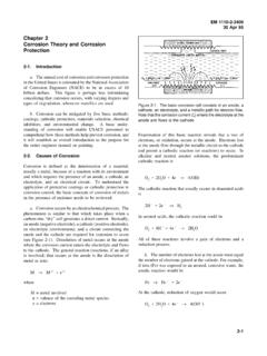
2 The smaller the zone, the greater the likelihood that good control will be achieved; however, equipment and maintenance costs are directly related to the number of zones. Some systems are designed to provide individual control of rooms in a multiple-zone system. Sometimes AHUs discharge (supply) and admit (return) air directly to and from the space served, without ductwork. They can be used in many other applications, for example, they can be used for providing smoke control, maintaining pressure relationships between spaces, and providing fresh air for occupants. All standard air handlers are designed to move a certain amount of air typically 400 cubic feet per minute (CFM) for 1 ton of refrigeration. Air Handling systems utilize various types of equipment, arranged in a specific order, so that space conditions can be maintained. Within each basic component there are different types and styles, each with their own operating characteristics and efficiency, method and materials of construction, and cost, all of which greatly affect the initial Design and resulting operating economics of the system.
3 2007 A. Bhatia Page 2 of 71 The units sizes range from small modular units of 2000 CFM to large custom built units of 30000 CFM and higher. Larger air handlers that condition 100% outside air, and no re-circulated air are known as makeup air units (MAUs). These are commonly used in places PDH Course M250 where the ventilation (outside air) load is very high. The roof top units (RTU) are other common air-handlers designed for outdoor use. These are usually mounted on roof curbs but can be also mounted on structural supports or on grade. These are particularly popular for single-story commercial buildings, warehouses and big stores. Supply air and return air ducts connect to the bottom (vertical discharge) or side (horizontal discharge) of the unit. Air Handling units are configured to be either blow-through or draw-through units.
4 Blow-through unit is when one of the coil sections is located downstream of the supply fan. Draw-through unit is when one of the coil sections is located upstream of the supply fan. Draw-through units can be further configured to be either horizontal units or vertical units. AHU Sizing Factors All Air Handlers are designed to heat and/or cool specific amount of air. The size of the unit is normally estimated to meet the load demands in British Thermal Units (BTUs) and a specific amount of air flow rate in Cubic Feet per Minute (CFM) at a designed static pressure or pressure drop. The amount of motor horsepower required to move this amount of air at the designed static load is then applied. Determine cooling & Heating load 2007 A. Bhatia Page 3 of 71 A load calculation determines the capacity of AHU, more specifically the capacity of the heating/ cooling coil.
5 The thermal load is estimated in units of BTUs. It factors in a number of criteria such as building square footage, physical makeup of the various envelope surfaces, solar load factors, construction materials, number of windows, lighting and indoor appliances, occupancy, and year-round weather concerns. The total cooling load for the space is determined by the summation of all of the calculated heat gains. Whilst the subjects of heat loads and air quantity or temperature calculations are fully dealt with in PDH course M-196, HVAC made easy a guide to heating and cooling load estimation and publications such as the ASHRAE guide, the cooling load calculations involves the following steps: PDH Course M250 1. Determine the zone cooling load . This consists of external loads through the building envelope and internal loads from people, lights, appliances, infiltration loads, moisture loads, and other heat sources.
6 2. calculate the system cooling load . This step adapts the selected air distribution system to the zone load and involves the introduction of the required outdoor air volume into the air conditioning system for ventilation. 3. calculate the Design temperature of supply air at the terminal (allowing for all normally calculated extraneous gains such as fan heat and duct wall heat pick-up) is arrived at by conventional psychometric calculations. 4. calculate the individual maximum module or zone air volumes are calculated using the maximum room sensible heat gain figure and the temperature difference between supply air temperature at the terminal and Design space temperature. These air volumes are then used to select air diffusers. 5. Maximum simultaneous cooling and air supply requirements are then computed in order to establish the capacity of air Handling units and central cooling equipment. Care must be taken in Design that ducting is adequately sized to convey the correct amount of air to every module or zone under all conditions.
7 A proper load calculation is important so that your system operates at maximum efficiency. Most facilities have systems that are oversized, so you end up paying more than you should to heat and cool your space. Also, systems that are improperly sized tend to cycle too quickly or too slowly and that can lead to maintenance problems, uneven temperatures, and an inability to control humidity. A properly sized system based on a correct load calculation can help ensuring long-lasting, reliable comfort in all seasons. Determine Airflow 2007 A. Bhatia Page 4 of 71 Air flow calculation determines the fan capacity, which in turn affects the physical size (foot print) of air Handling unit. This is single most important factor while conceptualizing the space requirements for mechanical rooms and also the air-distribution ducts. PDH Course M250 The volume of conditioned air depends on the heating, cooling and ventilation loads and is estimated in cubic feet per minute (CFM).
8 Once the airflow rate is determined next step is to estimate the static pressure drop across the distribution system comprising of ductwork, fittings and AHU components. When both air flow and static pressure is known, the appropriate fan selection is made. HVAC engineers use Psychrometric analysis for sizing the coils and for estimating the air flow rates required to be pushed into the ducting system. The psychrometric chart, a graphical representation of the thermodynamic properties of moist air, is an invaluable aid in illustrating and solving air conditioning problems. Let s refresh some elementary psychrometrics. PSYCHROMETRIC CHART Psychrometry deals with the determination of the thermodynamic properties of moist air and the utilization of these properties in the analysis of conditions and processes involving moist air. 2007 A. Bhatia Page 5 of 71 The basic coordinate grid lines of the chart are enthalpy, which slopes up to the left, and the humidity ratio (or specific humidity) which runs horizontal.
9 Dry-Bulb temperature is illustrated by vertical lines uniformly spaced. Wet-Bulb lines slope similarly to enthalpy lines, but the slope increases as the temperature increases. Note that wet-bulb line is not parallel to an enthalpy line; this is because of the heat added to the air mixture by the moisture, as it changes from dry to saturated air. Relative humidity lines are curved, with the saturation line defining the upper boundary of the chart. PDH Course M250 Psychrometric Parameters AIR- conditioning PROCESSES Common processes include: Sensible cooling /sensible heating cooling and dehumidification/heating and humidification Humidification/dehumidification 2007 A. Bhatia Page 6 of 71 Evaporative cooling /chemical dehydration PDH Course M250 Sensible Heating and cooling Sensible heating and cooling simply involve changing the dry bulb temperature of the moist air without changing the moisture content.
10 The humidity ratio remains unchanged, and so we use a horizontal line on the psychrometric chart to represent this process. This provides no control over the relative humidity and may produce conditions that are uncomfortable. Heating will result in lower relative humidity and cooling will result in a higher one. Sensible heating/ cooling process results in changes in dry-bulb, wet-bulb, RH, and enthalpy whereas specific humidity and dew-point temperature remain constant. Heating and Humidification In heating and humidifying both sensible heat and specific humidity increase-shown as a line sloping upward and to the right. Adding humidification is often necessary to make a heated space comfortable. One example of humidification is the adiabatic-saturation process, when air is passed over a moist surface to gain moisture by evaporation. In this case the dry bulb temperature could be increased or decreased, depending on the temperature of the evaporating water.