Transcription of HWH
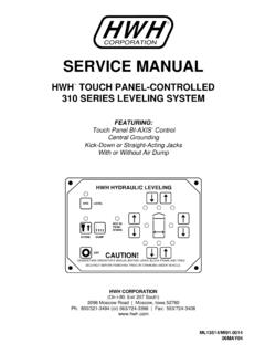
1 SERVICE MANUALHWH TOUCH PANEL-CONTROLLED305/325 SERIES LEVELING SYSTEM10 JAN05ML33832 : 800/321-3494 (or) 563/724-3396 | Fax: 563/724-34082096 Moscow Road | Moscow, Iowa 52760(On I-80, Exit 267 South)HWH CORPORATIONFEATURING:RSECURELY BEFORE REMOVING TIRES OR CRAWLING UNDER OPERATOR S MANUAL BEFORE USING. BLOCK FRAME AND TIRESCAUTION!HWH HYDRAULIC LEVELINGLEVELOFFSTORES traight-Acting JacksWith or Without Air DumpCentral GroundingBI-AXIS Hydraulic LevelingTouch Panel Leveling ControlRCORPORATIONWHHRSECTION PART FOLDERHOW TO USE MANUALB efore beginning your repair, it is IMPORTANT to read the CAUTIONS and NOTES AND CHECKS in the first section, TROUBLESHOOTING GUIDE. In many cases this will save time and mistakes when trouble shooting a Repair Manual is offered as a guide only.
2 It is impossible to anticipate every problem or combination of problems. Forany problems encountered that are not addressed in this manual, contact HWH Corporation for assistance. (800-321-3494)PROCEED WITH TROUBLE SHOOTING GUIDEThis manual is written in two sections. Section 1 is the Trouble Shooting Guide. Section 2 is the figures. Begin diagnosis of the system with Section 1, the Trouble Shooting Guide. The Trouble Shooting Guide describes system operation with each phase of operation followed by symptoms of possible problems. The problem section is broken into 3 columns, Problem, Solutions and Figures. Under Problems, find the symptom you have encountered. The testing and repair for that problem is in the Solution (center) column.
3 Diagrams for a particular Problem and Solution are in the Figures (right hand) column. This column will direct you to the proper figure in Section 2, Figures, for a more detailed !BLOCK FRAME AND TIRES SECURELY BEFORE CRAWLING UNDER VEHICLE. DO NOT USE THE LEVELINGJACKS OR AIR SUSPENSION TO SUPPORT VEHICLE WHILE UNDER VEHICLE OR CHANGING TIRES. VEHICLEMAY DROP AND OR MOVE FORWARD OR BACKWARD WITHOUT WARNING CAUSING INJURY OR ROUTING OR REROUTING HYDRAULIC HOSES AND WIRES, BE SURE THEY ARE NOT EXPOSED TO ENGINEEXHAUST OR ANY HIGH TEMPERATURE COMPONENTS OF THE PLACE HAND OR OTHER PARTS OF THE BODY NEAR HYDRAULIC LEAKS. OIL MAY CUT AND PENETRATE THE SKIN CAUSING INJURY OR CLASSES ARE TO BE WORN TO PROTECT EYES FROM DIRT, METAL CHIPS, OIL LEAKS, ECT.
4 FOLLOWALL OTHER SHOP SAFETY AND CHECKSRead and check before proceeding with Trouble Shooting : HWH CORPORATION ASSUMES NO LIABILITYFOR DAMAGES OR INJURIES RESULTING FROM THEINSTALLATION OR REPAIR OF THIS If the jacks cannot be retracted, see TROUBLE SHOOTINGStep 4h for temporary measures. Make sure the manualretract valves are closed before trouble The Trouble Shooting Guide must be followed in order. Problems checked for in one step are assumed correct and may not be checked again in following position. If the vehicle is equipped with HWH room4. Most coaches have more than one battery; one for the engineand the other(s) for the coach. The engine battery suppliespower for the control box and hydraulic pump.
5 Batteries underno load should read volts. Batteries must maintain good6. Do not replace the control box unless the Repair Steps sayto replace it. Otherwise the malfunctions may damage thenew control Proper grounding of all components is critical. See the electrical circuit for specific grounds required. Faulty grounds, especially for the control box, solenoid manifold or the pump assembly, may cause control box component damage and /or improper or erratic manual is intended for use by experienced mechanicswith knowledge of hydraulic and automotive electricalsystems. People with little or no experience with HWHleveling systems should contact HWH technical service(800-321-3494) before beginning.
6 Special attention shouldbe given to all cautions, wiring, and hydraulic note: When installing a new control box, makesure the box is properly grounded before applying powerto the tools for trouble shooting the HWH leveling systems:JUMPER WIRES (UP TO 10 GAUGE)PRESSURE GAUGE (3500 PSI MIN.)MULTI-METER12 VOLT TEST LIGHTPROCEED WITH THE TROUBLESHOOTING STEPS ON THEFOLLOWING PAGE3. Check that the oil reservoir is full with the jacks in the fullyvoltage under load. Batteries must be in good condition withno weak cells. An alternator, converter or battery charger willnot supply enough power for the system to operate hose end, tighten the hose end to snug plus 1/4tighten the hose end 1/3 turn (2 FLATS).
7 If tightening anmake the hose end snug (finger tight) on the fitting, thenTightening of hose ends: If tightening a new hose end,turn (1 FLAT).extensions, refer to the HWH Owners Manual for properposition of the room when checking the oil FUNCTIONS leveling system. CONTROL IDENTIFICATIONLEVEL MODE LIGHTWARNING LIGHTS (4-Red)CONTROL BUTTONSINDICATOR LIGHTSFRONT EXTEND BUTTONFRONT RETRACT BUTTONRIGHT SIDE RETRACT BUTTONRIGHT SIDE EXTEND BUTTON(The panel must be off before pressing the "STORE" button)extend their respective jack pairs to lift the SIDE EXTENDREAR EXTEND BUTTONREAR RETRACT BUTTONLEFT SIDE RETRACTLEVEL MODE LIGHT:"LEVEL" BUTTON:"OFF" BUTTON:"STORE" BUTTON:EXTEND BUTTONS (UP ARROWS):RETRACT BUTTONS (DOWN ARROWS):These buttons will This light indicates the system is inSTORE LIGHTSTORE LIGHT:the store BUZZER.
8 BUTTON"LEVEL" BUTTON"OFF" BUTTON"STORE" BUTTONBUTTONThis button places the system inleveling button turns off control power to theThis button will retract all four retract their respective jack pairs to lower the approximately 1/2 inch or more and the ignition This light will be on when the system is inA buzzer will sound if a jack is These buttonsswitch is in the "ON" HYDRAULIC LEVELINGCAUTION!UNDERSTAND OPERATOR S MANUAL BEFORE USING. BLOCK FRAME AND TIRESSECURELY BEFORE REMOVING TIRES OR CRAWLING UNDER leveling jacks are extended approximately 1/2 inch and themaster "JACKS DOWN" light which will be on when one orposition. Some vehicles are equipped with a dash mounted1/2 inch, provided the ignition is in the "ACC" or "ON" ever the corresponding jack is extended approximately A red WARNING light will be on when-ignition is in the "ON" LIGHTS:LEVEL LIGHTS (4-Yellow)If a yellow LEVELING light is on, thattwo yellow LEVELING lights can be on at a time.
9 The vehicle the appropriate jack pairs to put out the yellow light. One orindicates a side, corner, or end of the vehicle is low. Extendis level when all yellow lights are - Right Front and Left Front SIDE - Right Front and Right Rear SIDE - Left Front and Left Rear - Left Rear and Right Rear The Touch Panelhas a light on or canbe turned on with the ignition number 6122 on PIN 1 of CN1 on the touch panel should be connected to a +12 source on the accessory side Make sure the transmission is in the recommended position for parking and the park brake is set. With the ignition off,there should be no power to the leveling system. There should be no Touch Panel lights on. The pump should not be The pump 325 series leveling system is a manually operated system.
10 Push and hold the Up Arrow (EXTEND) buttons and Down Arrow (RETRACT) buttons to operate the jacks will always extend in pairs both front, both rear,right front and right rear or left front and left rear. Whentesting the system, always operate all 4 sets of assures the correct pair of jacks will extend or retractwhen their button is with an active air suspension will have an air dumpsystem. This will be an HWH system with several normallyclosed dump valves or a factory installed pilot air dumpsystem which is part of the chassis equipment. This manualwill discuss diagnostics of the vehicle is equipped with a pilot air dump system, the diagnostics for HWH is limited to a +12 Travel or Dump signal from the HWH Touch Panel and Control Box.