Transcription of HYBRID CONCRETE MASONRY CONSTRUCTION …
1 NCMA TEK 3-3B 1An information series from the national authority on CONCRETE MASONRY technologyHYBRID CONCRETE MASONRY CONSTRUCTION DETAILS TEK 3-3 BConstruction (2009)INTRODUCTION HYBRID MASONRY is a structural system that utilizes reinforced MASONRY walls with a framed structure. While the frame can be constructed of reinforced CONCRETE or structural steel, the discussion here includes steel frames with reinforced CONCRETE MASONRY walls. The reinforced MASONRY infi ll participates structurally with the frame and provides strength and stiffness to the system. It can be used in single wythe or cavity wall construc-tion provided the connections and joints are protected against water penetration and corrosion.
2 The HYBRID walls are constructed within the plane of the framing. Depending on the type of HYBRID wall used, the framing supports some or all of the MASONRY wall weight. HYBRID MASONRY /frame structures were fi rst pro-posed in 2006 (ref. 1). There are several reasons for its development but one primary reason is to simplify the CONSTRUCTION of framed buildings with MASONRY infi ll. While many designers prefer MASONRY infi ll walls as the backup for veneers in framed buildings, there is often a confl ict created when structural engineers design steel bracing for the frame which interferes with the MASONRY infi ll. This leads to detailing and construc-tion interferences trying to fi t MASONRY around braces.
3 One solution is to eliminate the steel bracing and use reinforced MASONRY infi ll as the shear wall bracing to create a HYBRID structural system. The concept of using MASONRY infi ll to resist lat-eral forces is not new; having been used successfully throughout the world in different forms. While common worldwide, based codes and standards have lagged behind in the establishment of standardized means of designing MASONRY infi ll. The HYBRID MASONRY system outlined in this TEK is a unique method of utilizing MASONRY infi ll to resist lateral forces. The novelty of the HYBRID MASONRY design approach relative to other more established infi ll design procedures is in the connection detailing between the MASONRY and steel frame, which offers multiple alterna-tive means of transferring loads into the MASONRY or isolating the MASONRY infi ll from the frame.
4 Prior to implementing the design procedures out-lined in this TEK, users are strongly urged to become familiar with the HYBRID MASONRY concept, its modeling assumptions, and its limitations particularly in the way in which inelastic loads are distributed during earthquakes throughout the MASONRY and frame system. This sys-tem, or design methods, should not be used in Seismic Design Category D and above until further studies and tests have been performed; and additional design guid-ance is outlined in adopted codes and OF WALLS There are three HYBRID wall types , Type I, Type II and Type III. The MASONRY walls are constructed within the plane of the framing.
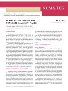
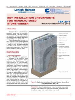
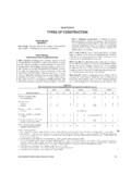
5 The classifi cation is dependent upon the degree of confi nement of the MASONRY within the frame. Type I walls have soft joints (gaps that allow lateral drift at the columns or vertical defl ection at the top) at the columns and the top of the wall. The framing sup-ports the full weight of the MASONRY walls and other gravity loads. Type II walls have soft joints at the columns and are built tight at the top of the wall. Type III walls are built tight at the columns and the top of the wall. For Type II and III walls, the MASONRY walls share the support of the vertical loads, including the wall weight, with the TEK:14-9 AKeywords: frame structures, infi ll, HYBRID , shear walls, tie-down, reinforced masonryPrepared in cooperation with the International MASONRY InstituteCONSTRUCTIONType I HYBRID Walls Practically speaking, the concept of Type I walls is that the MASONRY wall is a nonloadbearing shear wall built within the frame which also supports out-of-plane loads (see Figure 1).
6 The details closely match those for current cavity wall CONSTRUCTION where the infi ll MASONRY is within the plane of the frame, except that the vertical reinforcement must be welded to the perimeter framing at supported fl oors. Since the walls are generally designed to span vertically, the walls may not have to be anchored to the columns. The engineer s design should refl ect whether anchors are required but only for out-of-plane loads. The MASONRY does have to be isolated from the columns so the columns do not transmit loads to the walls when the frame drifts. In multi-story buildings, each wall is built indepen-dently.
7 Walls can be constructed on multiple fl oors simultaneously. Because the steel framing is supporting the entire wall weight, Type 1 walls are more economical for lower rise buildings. It is possible with Type 1 walls to position the walls outside the framing so they are foundation supported as in caged CONSTRUCTION (ref. 1), providing a more economical design for the II HYBRID Walls With Type ll walls, the MASONRY wall is essentially a loadbearing shear wall built within the frame: it supports both gravity and out-of-plane loads (see Fig. 1). There are two options: Type IIa and Type IIb. The engineer must indicate which will be used. For Type IIa walls, the vertical reinforcement (dowels) must be welded to the perimeter framing to transfer tension tie-down forces into the frame.
8 The vertical dowels also transfer shear. For Type IIb walls, vertical reinforcement only needs to be doweled to the CONCRETE slab to trans-fer shear forces because tie-down is not required. This simplifi es the CONSTRUCTION of multi-story buildings. The top of the MASONRY wall must bear tight to the framing. Options include grouting the top course, using solid units, or casting the top of the wall. The top connectors must extend down from the framing to overlap with the vertical wall reinforcement. Since the walls generally span vertically, the engi-neer must decide whether column anchors are needed similar to Type I walls. These anchors only need to transmit out-of-plane loads.
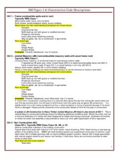
9 The design must take into account the construc-tion phasing. In multi-story buildings, each wall may be structurally dependent on a wall from the fl oor below which is very similar to a loadbearing MASONRY building. 2 NCMA TEK 3-3 BFigure 1 HYBRID Wall types I and IIType III HYBRID Walls This wall type is fully confi ned within the framing at beams and columns. Currently, there are no standards in the United States that govern Type III design. Standards are under development and research is underway to help determine structural and CONSTRUCTION requirements. Therefore, no details are provided at this Sample CONSTRUCTION details were developed in conjunction with the National CONCRETE MASONRY As-sociation, International MASONRY Institute (IMI), and David Biggs.
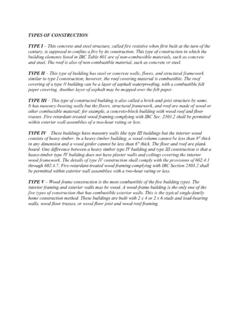
10 They are hosted on the NCMA web site at and the IMI web site at Alternate details for HYBRID CONSTRUCTION are continually under development and will be posted on the web sites. There are several key details that must be considered, including: the wall base, the top of the wall, at columns, and parapets. Type I HYBRID WallType II HYBRID WallBase of Wall As previously noted for Type I and Type IIa walls, vertical reinforcement must be anchored to either foundation or frame to provide tension-tie downs for the structure. Figure 2 shows the reinforcement anchored to the foundation with a tension lap splice, and also shows the reinforcement anchored at a fl oor level and tension lap spliced.