Transcription of KEY INSTALLATION CHECKPOINTS FOR MANUFACTURED …
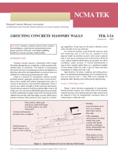
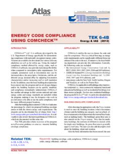
1 An information series from the national authority on concrete masonry technologyNCMA TEK 20-1 1 KEY INSTALLATION CHECKPOINTS FOR MANUFACTURED STONE VENEERTEK 20-1 MANUFACTURED Stone veneer (2014)INTRODUCTION MANUFACTURED stone veneer has the ap-pearance of natural stone, but is manufac-tured from concrete. The veneer is increas-ing in popularity and being used aesthetically for commercial and residential applications, giving buildings a rich, upscale look. Typical installations are shown in Fig-ures 1 and 2 for concrete masonry and wood frame applications, respectively. There are a number of key INSTALLATION /inspection points that must be followed to provide a properly performing system . This TEK ad-dresses a number of those key points. KEY INSTALLATION /INSPECTION POINTS1. Substrate PreparationWood- and Metal-Framed Applications According to The Engineered Wood Association s (APA) INSTALLATION of Stuc-co Exterior Over Wood Structural Panel Wall Sheathing (ref.)
2 1), when wood struc-tural panel sheathing (plywood or oriented strand board OSB) is used as the substrate material, it must have a 1/8 in. (3 mm) gap between the sheets on all sides to accom-modate wood sheathing expansion when it gets wet. Without the gap, wood swelling will cause the adhered masonry veneer fin-ish to crack, compromising the water resis-tance of the finish. This will allow water entry and degradation of the substrate, the veneer and the framing. Additionally, the wood framing should be relatively dry at the time of INSTALLATION , as drying of the wet substrate causes shrinkage which could lead to cracking of the finish. Also note that Keywords: adhered concrete masonry veneer , brown coat, construction, inspection, lath, MANUFACTURED stone veneer , metal lath, mortar setting bed, scratch coat, veneer , water resistive barrier, weep screedFigure 1 Application of Adhered Concrete masonry veneer Over Concrete masonry With Lath2 NCMA TEK 20-1the International Building Code (ref.
3 11) limits the deflection of wall systems to L/240 for brittle finishes. Concrete and Concrete masonry Walls MANUFACTURED stone veneer can be directly applied to surfaces of concrete and concrete masonry if they are free of dirt, waterproofing, paint, form oil, or any other substance that could inhibit the mortar bond. They must have a rough texture to ensure a mortar bond. ICRI guideline number 03732 (ref. 5) discusses Concrete Surface Profile (CSP), a standardized method to measure concrete surface roughness. An ICRI CSP equal to or greater than 2 is usually acceptable. Typically, cleaning may be done with power washing and/or mechanical methods ( shot or bead blasting). If a bondable surface cannot be achieved, attach lath and a scratch coat be-fore installing MANUFACTURED stone veneer . Do not bond man-ufactured stone masonry veneer to clay masonry surfaces. 2. Water Management ASTM C1780, Standard Practice for INSTALLATION Methods for Adhered MANUFACTURED Stone masonry veneer , (ref.
4 3) re-quires two separate layers of water-resistive barrier (WRB) to be installed over wood sheathing in exterior applications. The standard also requires that the two separate layers be installed in shingle fashion. Starting from the bottom of the wall, the inner layer of WRB should be installed, along with flashings, to create a drainage plane. The upper layer of the WRB should lap the top of the lower layer by a minimum of 2 in. (51 mm). The vertical joints of the WRB must be lapped a minimum of 6 in. (152 mm). Inside and outside corners must be overlapped a minimum of 16 in. (406 mm) past the corner in both directions. The WRB should be installed in accordance with the manufac-turer s recommendations and be integrated with all flashing ac-cessories, adjacent WRBs, doors, windows, penetrations, and cladding transitions. The outer layer of WRB is intended to keep the scratch coat from contacting the inner layer of WRB and may be of a different material than the inner Wall Systems: Drainage wall systems also are a very effective means of keeping water from penetrating to the interior and diverting it to the exterior.
5 These systems have a minimum drainage gap of 3 16 in. (5 mm) and a maximum drainage gap of 3 4 in. (19 mm). When a system of this type is used, some building codes permit the use of a single WRB. Other CHECKPOINTS for effective water management include:a. flashing at all penetrations, terminations and transitions, in-tegrated with the WRB and water directed out of the system ,b. proper overhang of capping materials, andc. soft joints at dissimilar materials to accommodate some movement and minimize incidental water Proper Selection of Metal Lath by Weight and Style for Each Span and Application ASTM C1063, Standard Specification for INSTALLATION of Lathing and Furring to Re-ceive Interior and Exterior Portland Cement-Based Plaster (ref. 4) must be followed for a properly performing MANUFACTURED stone ve-neer system . All lath must be self-furred or use self-furring fasteners to allow the mortar to completely fill and encase the lath.
6 All lath and lath accessories must be corro-sion resistant, consisting of either galvanized or stainless steel materials or nonmetallic lath with a published evaluation report from an ANSI accredited evaluation service and be rated for use behind MANUFACTURED stone ve-neer. More detailed recommendations can be found in the INSTALLATION Guide for Adhered Concrete masonry veneer (ref. 2).4. Proper INSTALLATION of Metal Lath The INSTALLATION of lath should be in accor-dance with ASTM C1063-14a (current ver-sion), Standard Specification for INSTALLATION of Lathing and Furring to Receive Interior and Exterior Portland Cement-Based Plaster (ref. 4). Metal lath should be applied horizon-tally (perpendicular to framing, if present) per manufacturer s instructions, and should over-lap a minimum of 1 in. (25 mm) at the vertical seams and a minimum of 1/2 in. (13 mm) at the horizontal seams. The ends of adjoining lath places should be staggered.
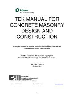
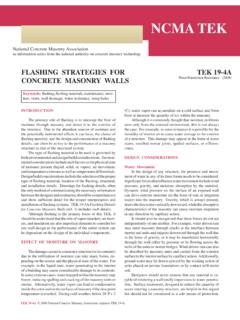
7 Lath should be wrapped around inside and outside corners a minimum of 12 in. (305 mm). Lath should Figure 2 Application of Adhered Concrete masonry veneer Over Wood Frame With Structural Wood SheathingNCMA TEK 20-1 3be fastened every 7 in. (178 mm) vertically on each stud. The spacing of studs should not exceed 16 in. (406 mm). A similar spacing should be used on concrete or masonry wall surfaces. Do not end lath at inside/outside corner framing. If not installed in accordance with ASTM C1063, alter-nate lath INSTALLATION practices should be in accordance with manufacturer s instructions. Acceptable INSTALLATION practices for metal lath should be evaluated in accordance with AC191, Acceptance Criteria for Metal Plaster Bases (Lath) (ref. 12). While recommendations vary, existing codes and stan-dards do not stipulate the orientation of the lath cups (keys) once installed. More important than the orientation of the lath cups is ensuring the lath is embedded within, and bonded to, the mortar scratch coat for a successful AMSV INSTALLATION .
8 Lath is considered to be embedded within the mortar scratch coat when there is a 1/4 in. (6 mm) nominal thickness of mortar between the back plane of the lath and the back plane of the scratch coat for at least one-half (50%) of the surface area of the INSTALLATION . When lapping paperbacked lath, be sure that lath is against lath and paper against paper. Paper backing inserted between lath at laps will prevent the mortar from going into the second lath and won t lock the two sheets together. This can cause cracking in the MANUFACTURED stone veneer at the lath joint. In the summer months, paperbacked lath must be pro-tected from the sun and extreme heat to prevent the glue that attaches the paper to the lath from melting. 5. Proper Fastening of Lath Proper fastener spacing and penetration is critical. Cor-rosion resistant fasteners (ref. 4) require a minimum 3/4 in. ( mm) nail penetration into wood framing members, a minimum 3/4 in.
9 ( mm) staple penetration into wood framing members, or minimum a 3/8 in. ( mm) penetration of metal framing members. Fasteners must have heads large enough to properly engage the lath. Note that fasteners must be anchored into the framing members and are to be spaced no more than 7 in. (178 mm) on center per ASTM C1063 (ref. 4). Wood and gypsum sheath-ing do not have enough holding power to fully support the lath and MANUFACTURED stone veneer . A fastener attached only to the sheathing can work loose, particularly if the sheathing becomes wet. Proper fastening will help ensure that the ve-neer does not become detached during high wind events. Fastener type and size is also very important. For INSTALLATION directly to wood framing members, ASTM C1063 allows for the use of 11/2 in. (38 mm) roofing nails to horizontal framing mem-bers. Vertical applications require the use of 1-in. (25-mm) roof-ing nails, 1-in.
10 (25-mm) staples with minimum 3/4-in. (19-mm) crowns, or 6d common nails driven to a penetration of at least 3/4 in. (19 mm) and bent over to engage at least three strands of lath. Where welded or woven wire lath is installed, rest the wire on the fastener for best performance rather than install-ing the fastener above the wire. For fastening lath to steel supports, reference is made to ASTM C954 (ref. 6) by ASTM C1063 for screw information. Per that standard, lath can be wire-tied to the member with 18-gauge tie wire. Whether wire or screws are used, the maxi-mum allowed spacing should be maintained, and once again all fastening must be corrosion resistant and penetrate into the structural member. ASTM C954 also states that the screw shall have a minimum head size of 7/16 in. (11 mm) with either a pan or wafer head large enough to engage at least three strands of lath.