Transcription of I2S bus specification - SparkFun Electronics
1 Philips SemiconductorsI2S bus specification1 February 1986 Revised: June 5, INTRODUCTIONMany digital audio systems are being introduced into the consumeraudio market, including compact disc, digital audio tape, digitalsound processors, and digital TV-sound. The digital audio signals inthese systems are being processed by a number of (V)LSI ICs,such as: A/D and D/A converters; digital signal processors; error correction for compact disc and digital recording; digital filters; digital input/output communication structures are vital for both theequipment and the IC manufacturer, because they increase systemflexibility.
2 To this end, we have developed the inter-IC sound (I2S)bus a serial link especially for digital BASIC SERIAL BUS REQUIREMENTSThe bus has only to handle audio data, while the other signals, suchas sub-coding and control, are transferred separately. To minimizethe number of pins required and to keep wiring simple, a 3-line serialbus is used consisting of a line for two time-multiplexed datachannels, a word select line and a clock the transmitter and receiver have the same clock signal fordata transmission, the transmitter as the master, has to generate thebit clock, word-select signal and data.
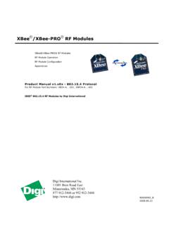
3 In complex systems however,there may be several transmitters and receivers, which makes itdifficult to define the master. In such systems, there is usually asystem master controlling digital audio data-flow between thevarious ICs. Transmitters then, have to generate data under thecontrol of an external clock, and so act as a slave. Figure 1illustrates some simple system configurations and the basicinterface timing. Note that the system master can be combined witha transmitter or receiver, and it may be enabled or disabled undersoftware control or by pin SCKword select WSdata SDRECEIVERTRANSMITTER = MASTERTRANSMITTERSCKWSSDRECEIVERRECEIVER = MASTERTRANSMITTERSCKWSSDRECEIVERCONTROLL ER = MASTERCONTROLLERSCKWSSDWORD n 1 RIGHT CHANNELWORD n+1 RIGHT CHANNELWORD nLEFT CHANNELLSBMSBMSBSN00119 Figure 1.
4 Simple System Configurations and Basic Interface TimingPhilips SemiconductorsI2S bus specificationFebruary THE I2S BUSAs shown in Figure 1, the bus has three lines: continuous serial clock (SCK); word select (WS); serial data (SD);and the device generating SCK and WS is the Serial DataSerial data is transmitted in two s complement with the MSB MSB is transmitted first because the transmitter and receivermay have different word lengths. It isn t necessary for the transmitterto know how many bits the receiver can handle, nor does thereceiver need to know how many bits are being the system word length is greater than the transmitter wordlength, the word is truncated (least significant data bits are set to 0 )for data transmission.
5 If the receiver is sent more bits than its wordlength, the bits after the LSB are ignored. On the other hand, if thereceiver is sent fewer bits than its word length, the missing bits areset to zero internally. And so, the MSB has a fixed position, whereasthe position of the LSB depends on the word length. The transmitteralways sends the MSB of the next word one clock period after theWS data sent by the transmitter may be synchronized with eitherthe trailing (HIGH-to-LOW) or the leading (LOW-to-HIGH) edge ofthe clock signal .
6 However, the serial data must be latched into thereceiver on the leading edge of the serial clock signal , and so thereare some restrictions when transmitting data that is synchronizedwith the leading edge (see Figure 2 and Table 1). Word SelectThe word select line indicates the channel being transmitted: WS = 0; channel 1 (left); WS = 1; channel 2 (right).WS may change either on a trailing or leading edge of the serialclock, but it doesn t need to be symmetrical. In the slave, this signalis latched on the leading edge of the clock signal .
7 The WS linechanges one clock period before the MSB is transmitted. This allowsthe slave transmitter to derive synchronous timing of the serial datathat will be set up for transmission. Furthermore, it enables thereceiver to store the previous word and clear the input for the nextword (see Figure 1). TIMINGIn the I2S format, any device can act as the system master byproviding the necessary clock signals. A slave will usually derive itsinternal clock signal from an external clock input. This means, takinginto account the propagation delays between master clock and thedata and/or word-select signals, that the total delay is simply thesum of: the delay between the external (master) clock and the slave sinternal clock; and the delay between the internal clock and the data and/orword-select data and word-select inputs, the external to internal clock delayis of no consequence because it only lengthens the effective set-uptime (see Figure 2).
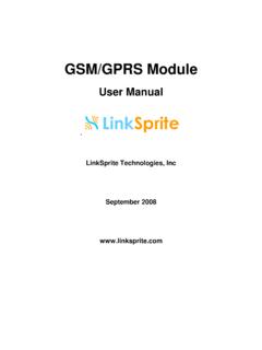
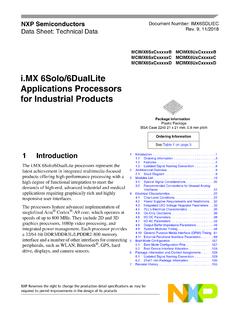
8 The major part of the time margin is toaccommodate the difference between the propagation delay of thetransmitter, and the time required to set up the timing requirements are specified relative to the clock period or tothe minimum allowed clock period of a device. This means thathigher data rates can be used in the *tLC = = 0tdtr = clock periodTtr= minimum allowed clock period for transmitterT>Ttr tRC is only relevant for transmitters in slave 2. Timing for I2S TransmitterPhilips SemiconductorsI2S bus specificationFebruary 19863 SDandWSSCKTtLC = = = clock periodTr= minimum allowed clock period for transmitterT>Trtsr 0SN00121 Figure 3.
9 Timing for I2S ReceiverNote that the times given in both Figures 2 and 3 are defined by the transmitter speed. The specification of the receiver has to be able to matchthe performance of the transmitterExample: Master transmitter with data rate of ( 10%) (all values in ns)MINTYPMAXCONDITION clock period T360400440 Ttr = 360clock HIGH tHC160min > = 140 (at typical data rate)clock LOW tLC160min > = 140 (at typical data rate)delay tdtr300max < = 320 (at typical data rate)hold time thtr100min > 0clock rise-time tRC60max > = 54 (only relevant in slave mode)Example.
10 Slave receiver with data rate of ( 10%) (all values in ns)MINTYPMAXCONDITION clock period T360400440 Ttr = 360clock HIGH tHC110min < = 126clock LOW tLC110min < = 126set-up time tsr60min < = 72hold time thtr0min < 0 Philips SemiconductorsI2S bus specificationFebruary 19864 Table 1. Timing for I2S transmitters and receiversTRANSMITTERRECEIVERLOWER LIMITUPPER LIMITLOWER LIMITUPPER LIMITMINMAXMINMAXMINMAXMINMAXNOTESC lock period TTtrTr1 MASTER MODE:clock generated by transmitter or receiver:HIGH MODE:clock accepted by transmitter or receiver:HIGH :delay time thtr03 RECEIVER:set-up time time thr05 All timing values are specified with respect to high and low threshold :1.