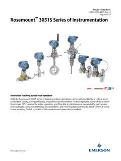
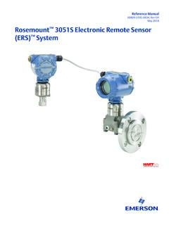
Transcription of Includes Transmitter Option TR - Emerson Electric
1 Manual 00809-0100-4051, Rev AAJanuary 2007 Rosemount 3051 Pressure Transmitter Includes Transmitter Option TRProduct DiscontinuedReference Manual 00809-0100-4051, Rev AAJanuary 2007 Rosemount 3051 Pressure Transmitter ..NOTICERead this manual before working with the product. For personal and system safety, and for optimum product performance, make sure you thoroughly understand the contents before installing, using, or maintaining this technical assistance, contacts are listed below:Customer CentralTechnical support, quoting, and order-related States - 1-800-999-9307 (7:00 am to 7:00 pm CST) Asia Pacific- 65 777 8211 Europe/ Middle East/ Africa - 49 (8153) 9390 North American Response CenterEquipment service (24 hours Includes Canada)Outside of these areas, contact your local Rosemount products described in this document are NOT designed for nuclear-qualified applications.
2 Using non-nuclear qualified products in applications that require nuclear-qualified hardware or products may cause inaccurate information on Rosemount nuclear-qualified products, contact your local Rosemount Sales Manual 00809-0100-4051, Rev AAJanuary 2007 TOC-1 Rosemount 3051 SECTION 1 IntroductionUsing This Manual .. 1-1 Models Covered .. 1-2 Transmitter Overview .. 1-3 Service Support .. 1-4 SECTION 2 InstallationOverview.. 2-1 Safety Messages .. 2-1 Warnings .. 2-1 General Considerations .. 2-2 Mechanical Considerations.. 2-2 Draft Range Considerations .. 2-3 Environmental Considerations.
3 2-3 Installation Procedures .. 2-5 Mount the Transmitter .. 2-6 Process Connections.. 2-11 Housing Rotation.. 2-12 LCD Display Rotation .. 2-13 Configure Security and Alarm .. 2-14 Connect Wiring and Power Up .. 2-16 Optional Transient Protection Terminal Block .. 2-17 Grounding the Transmitter Case .. 2-17 Rosemount 305, 306 and 304 manifolds .. 2-18 Rosemount 305 Integral Manifold Installation Procedure .. 2-19 Rosemount 306 Integral Manifold Installation Procedure .. 2-19 Rosemount 304 Conventional Manifold Installation Procedure.. 2-19 Integral Manifold Operation .. 2-20 SECTION 3 ConfigurationOverview.
4 3-1 Safety Messages .. 3-1 Warnings .. 3-1 Commissioning On The Bench With HART .. 3-2 Setting the Loop to Manual .. 3-2 Wiring Diagrams .. 3-3 Configuration Data Review.. 3-4 HART Communicator .. 3-5 Menu Tree .. 3-5 Fast Key Sequence .. 3-6 Check Output .. 3-7 Process Variables .. 3-7 Sensor Temperature .. 3-7 Basic Setup.. 3-8 Set Process Variable Units .. 3-8 Set Output (Transfer function).. 3-8 Rerange.. 3-9 Damping .. 3-12 LCD Display .. 3-12 LCD Display Configuration .. 3-12 Table of ContentsReference Manual00809-0100-4051, Rev AAJanuary 2007 Rosemount 3051 TOC-2 Detailed Setup.
5 3-13 Failure Mode Alarm and Saturation .. 3-13 Alarm and Saturation Level Configuration .. 3-14 Alarm and Saturation Levels for Burst Mode .. 3-14 Alarm and Saturation Values for Multidrop Mode.. 3-15 Alarm Level Verification .. 3-15 Process Alerts .. 3-15 Scaled Variable Configuration .. 3-16Re-mapping .. 3-19 Sensor Temperature Unit .. 3-19 Diagnostics and Service .. 3-20 Transmitter Test .. 3-20 Loop Test .. 3-20 Advanced Functions for HART Protocol .. 3-22 Saving, Recalling, and Cloning Configuration Data .. 3-22 Burst Mode .. 3-24 Multidrop Communication .. 3-25 Changing a Transmitter Address.
6 3-26 Communicating with a Multidropped Transmitter .. 3-26 Polling a Multidropped Transmitter .. 3-26 SECTION 4 Operation and MaintenanceOverview .. 4-1 Calibration for HART Protocol .. 4-1 Calibration Overview .. 4-2 Determining Calibration Frequency .. 4-4 Choosing a Trim Procedure .. 4-5 Sensor Trim Overview .. 4-5 Zero Trim .. 4-6 Sensor Trim .. 4-6 Recall Factory Trim Sensor Trim .. 4-7 Analog Output Trim .. 4-8 Digital-to-Analog Trim.. 4-8 Recall Factory Trim Analog Output .. 4-10 Compensating for Line Pressure .. 4-10 Diagnostic Messages .. 4-12 SECTION 5 TroubleshootingOverview.
7 5-1 Safety Messages .. 5-1 Warnings .. 5-1 Disassembly Procedures.. 5-3 Remove from Service.. 5-3 Remove Terminal Block .. 5-3 Remove Interface Assembly.. 5-4 Remove the Sensor Module from the Housing.. 5-4 Reassembly Procedures .. 5-5 Attach the Sensor Module to the Housing .. 5-5 Install Interface Assembly.. 5-5 Install the Terminal Block .. 5-5 Reassemble the Process Flange .. 5-6 Safety Messages .. 6-1 Warnings .. 6-1 Reference Manual 00809-0100-4051, Rev AAJanuary 2007 TOC-3 Rosemount 3051 SECTION 6 Safety Instrumented SystemsCertification .. 6-23051 Safety Certified Identification.
8 6-2 Installation .. 6-2 Commissioning .. 6-2 Damping .. 6-3 Alarm and Saturation Levels .. 6-3 Operation and Maintenance .. 6-5 Proof Test.. 6-5 Inspection .. 6-6 Specifications.. 6-6 Failure Rate Data .. 6-6 Product Life .. 6-6 Spare Parts .. 6-6 APPENDIX AReference DataPerformance Specifications..A-1 Reference Accuracy ..A-1 Total Performance ..A-2 Long Term Stability..A-2 Dynamic Performance ..A-2 Line Pressure Effect per 1000 psi (6,9 MPa) ..A-3 Ambient Temperature Effect per 50 F (28 C) ..A-3 Mounting Position Effects..A-3 Vibration Effect ..A-3 Power Supply Effect ..A-3 Electromagnetic Compatibility (EMC).
9 A-3 Transient Protection ( Option Code T1)..A-4 Functional Specifications..A-4 Range and Sensor Limits ..A-4 Service ..A-5 HART 4 20 mA (Output Code A) ..A-5 Overpressure Limits ..A-6 Static Pressure Limit..A-7 Burst Pressure Limits ..A-7 Temperature Limits..A-7 Humidity Limits ..A-8 Turn-On Time ..A-8 Volumetric Displacement ..A-8 Damping ..A-8 Failure Mode Alarm ..A-9 Physical Specifications ..A-9 Electrical Connections ..A-9 Process Connections ..A-9 Process-Wetted Parts..A-10 Rosemount 3051L Process Wetted Parts ..A-10 Non-Wetted Parts..A-11 Dimensional Drawings..A-12 Ordering Information.
10 A-21 options ..A-30 Shipping Weights ..A-32 Parts List ..A-34 Spare Parts ..A-38 Product Compatibility..A-41 Reference Manual00809-0100-4051, Rev AAJanuary 2007 Rosemount 3051 TOC-4 Revision Level Indicators ..A-413051 Safety Certified Identification ..A-41 Revision Level Indicators ..A-41 APPENDIX BApproval InformationOverview ..B-1 Safety Messages ..B-1 Warnings ..B-1 Approved Manufacturing Locations ..B-2 European Directive Information ..B-2 ATEX Directive ..B-2 European Pressure Equipment Directive (PED) (97/23/EC) ..B-3 Electro Magnetic Compatibility (EMC) ..B-3 Other important guidelines.


