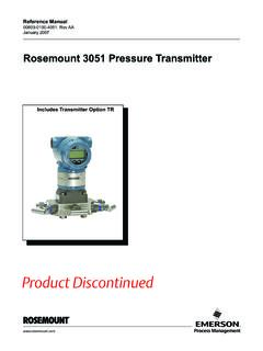
Transcription of Manual: Rosemount 3051S Electric Remote Sensor System
1 Reference Manual00809-0100-4804, Rev DAMay 2018 Rosemount 3051S Electronic Remote Sensor (ERS) SystemiReference manual 00809-0100-4804, Rev DAContentsMay 2018 Contents 1 Section 1: this manual .. recycling/disposal .. 1 2 Section 2: .. messages.. covered .. procedures .. Rosemount ERS Sensors .. each Rosemount ERS Sensor .. connections .. housing orientation.. security and alarm .. wiring and power up .. manifolds .. 305 Manifold installation procedure .. 304 Manifold installation procedure .. 306 Manifold installation procedure .. valve configurations .. 23 3 Section 3: .. messages.. the loop to manual .
2 Diagrams.. setup .. tagging .. of measure.. 27 ContentsiiReference Manual00809-0100-4804, Rev DAContentsMay mapping .. output .. and saturation levels .. configuration .. display .. mode .. communication .. variable .. assignments .. alerts.. menu trees .. 39 4 Section 4: Operation and .. messages.. overview .. and PLO Sensor calibration .. calibration .. output trim .. factory trim .. tests .. device .. upgrades and replacements .. considerations .. the terminal block.. the electronics .. the SuperModule from the housing .. the SuperModule to the housing .. electronics assembly.
3 The terminal block.. the process flange .. 52 5 Section 5: .. overview .. 55iiiReference manual 00809-0100-4804, Rev DAContentsMay host diagnostics.. display diagnostics .. quality status .. support.. 59 6 Section 6: Safety Instrumented Systems Instrumented Systems (SIS) Certification .. ERS Systems safety certified identification .. in SIS applications .. in SIS applications .. 3051S SIS operation and maintenance.. 63 AAppendix A: Reference Certifications .. Information, Specifications, and Drawings .. 65ivReference Manual00809-0100-4804, Rev DAContentsMay 2018 ContentsvReference manual 00809-0100-4804, Rev DATitle PageMay 2018 Title PageRosemount 3051S Electronic Remote Sensor (ERS) SystemNOTICERead this manual before working with the product.
4 For personal and System safety, and for optimum product performance, make sure you thoroughly understand the contents before installing, using, or maintaining this technical assistance, contacts are listed below:Customer CentralTechnical support, quoting, and order-related 1 800 999 9307 Europe +41 (0) 41 768 6111 Middle east +971 4 811 8100 Asia +65 6777 8211 North American Response CenterEquipment service (24 hours includes Canada)Outside of these areas, contact your local Emerson products described in this document are NOT designed for nuclear-qualified applications. Using non-nuclear qualified products in applications that require nuclear-qualified hardware or products may cause inaccurate information on Rosemount nuclear-qualified products, contact your local Emerson Sales Manual00809-0100-4804, Rev DATitle PageMay 2018 Title PageFailure to follow these installation guidelines could result in death or serious sure only qualified personnel perform the could result in death or serious injury.
5 Do not remove the housing covers in explosive atmospheres when the circuit is live. Before connecting a Field Communicator in an explosive atmosphere, make sure the instruments in the loop are installed in accordance with intrinsically safe or non-incendive field wiring practices. Both housing covers must be fully engaged to meet flameproof/explosion-proof requirements. Verify the operating atmosphere of the transmitter is consistent with the appropriate hazardous location certifications. Electrical shock could cause death or serious injury. If the Rosemount ERS System is installed in a high-voltage environment and a fault or installation error occurs, high voltage may be present on the Sensor leads and terminals.
6 Use extreme caution when making contact with the leads and terminals. Process leaks could result in death or serious injury. Install and tighten all four flange bolts before applying pressure. Do not attempt to loosen or remove flange bolts while the Rosemount ERS System is in service. Replacement equipment or spare parts not approved by Emerson for use as spare parts could reduce the pressure retaining capabilities of the transmitter and may render the instrument dangerous. Use only bolts supplied or sold by Emerson as spare parts. Improper assembly of manifolds to traditional flange can damage the the safe assembly of the manifold to the Sensor flange, bolts must break the back plane of the flange web ( bolt hole) but must not contact the Sensor module.
7 Static electricity can damage sensitive safe handling precautions for static-sensitive manual 00809-0100-4804, Rev DAIntroductionMay 2018 IntroductionSection this manualThe sections in this manual provide information on installing, operating, and maintaining a Rosemount 3051S Electronic Remote Sensor (ERS) System with HART protocol. The sections are organized as follows: Section 2: Installation contains mechanical and electrical installation instructions, and field upgrade options. Section 3: Configuration provides instruction on commissioning and operating a Rosemount ERS System . Information on software functions, configuration parameters, and online variables is also included.
8 Section 4: Operation and Maintenance contains operation and maintenance techniques. Section 5: Troubleshooting provides troubleshooting techniques for the most common operating problems. Section 6: Safety Instrumented Systems Requirements contains all certification and operation information for SIS applications. Appendix A: Reference Data supplies reference and specification data as well as ordering information. recycling/disposalRecycling of equipment and packaging should be taken into consideration and disposed of in accordance with local and national Manual00809-0100-4804, Rev DAIntroductionMay 2018 Introduction3 Reference manual 00809-0100-4804, Rev DAInstallationMay 2018 InstallationSection 2 InstallationOverview.
9 Page 3 Safety messages .. page 3 Models covered .. page 4 Installation procedures .. page 8 Rosemount manifolds .. page section covers installation considerations for the Rosemount 3051S Electronic Remote Sensor (ERS) System . A Quick Start Guide is shipped with every Rosemount 3051S ERS Transmitter to describe basic installation, wiring, configuration, and startup procedures. Dimensional drawings for each Rosemount 3051S ERS Transmitter are included in Product Data messagesProcedures and instructions in this section may require special precautions to ensure the safety of personnel performing the operation. Information that raises potential safety issues is indicated with a warning symbol ().
10 Refer to the following safety messages before performing an operation preceded by this to follow these installation guidelines could result in death or serious sure only qualified personnel perform the could result in death or serious injury. Do not remove the housing covers in explosive atmospheres when the circuit is live. Before connecting a Field Communicator in an explosive atmosphere, make sure the instruments in the loop are installed in accordance with intrinsically safe or non-incendive field wiring practices. Both housing covers must be fully engaged to meet flameproof/explosion-proof requirements. Verify the operating atmosphere of the transmitter is consistent with the appropriate hazardous location certifications.


