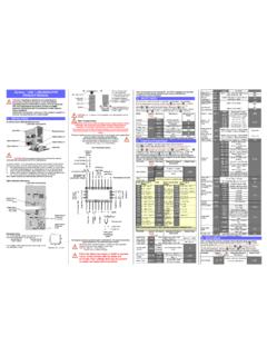
Transcription of industrialautomation Series Temperature Controller ...
1 Series Temperature Controller Instruction sheet Thank you very much for choosing Delta DTD Series Temperature Controller . Please read this instruction sheet before using your DTD to ensure proper operation. Keep this instruction sheet handy for quick reference. Warning DANGER! CAUTION! ELECTRIC SHOCK! When the power is on, DO NOT touch the AC terminals in case an electric shock may occur. Make sure the power is disconnected when you check the input power. DTD is an OPEN-TYPE device. If it will cause serious injury to workers or damage on other equipments when used in a dangerous environment, please make sure it is installed in an automatic safety protection device.
2 1. Always use recommended solder-less terminals: Fork terminal with isolation (M3 screw, Max. width ). Please be sure to tighten them properly and make sure the wire is connected to the correct terminal. 2. Prevent dust or metallic debris from falling into the device and cause malfunctions. DO NOT modify or uninstall DTD Series without being permitted. DO NOT use empty terminals. 3. Keep away from high-voltage and high-frequency environment during installation in case of interference. Prevent using the device in premises which contain: (a) dust or corrosive gas; (b) high humidity and high radiation; (c) shock and vibration 4.
3 The power has to be switched off when wiring or changing Temperature sensor. 5. Make sure to use compensation wire which matches the thermocouple when extending or connecting the thermocouple wire. 6. Use wires with resistance when extending or connecting the platinum resistance sensor. 7. Keep the wire as short as possible when wiring a sensor to the Temperature Controller . Separate the power cable and load wire in order to prevent interference and induced noise. 8. DTD is an open-type device. Make sure to install it in an enclosure which prevents dust and humidity in case of an electric shock.
4 9. Make sure the power cables and signal device are installed correctly before switching on the power; otherwise serious damage may occur. 10. DO NOT touch the terminals or repair the device when the power is on; otherwise an electric shock may occur 11. Please wait for one minute after the power is switched off to allow the capacitor to discharge and DO NOT touch the internal wiring within this period. Use dry cloth to clean the device. DO NOT use acid or alkaline liquid to clean the device. Display, LED & Pushbuttons PV Present value/function display(red 7-segment LED) SV Set value (green 7-segment LED) AT Flashes when PID auto-tuning(green LED) OUT On when output (green LED) ALM On when alarm (red LED) Selecting modes completing setup Displaying functions Left-shifting the digit Ordering Information DTD012345 Series name DTD: Delta D Series Temperature Controller 1!
5 Up key 234 Panel size (W H) 4848: 1/16 DIN W48 H48 mm 4896: 1/8 DIN W48 H96 mm 7272: W72 H72 mm 5 R: Relay output SPST (250 VAC, 5A) V: Voltage pulse output 14V +10% ~ -20% (Max. 40mA) Optional 0: None Specifications Power input AC100 ~ 240V 50/60Hz Input power range 85% ~ 110%, rated voltage Power consumption 6VA Max. Display 7-segment LED; PV in red, SV in green Input Temperature sensor Thermocouple: K, J, T, E, N, R, S, B, U, L, Txk Platinum resistance: Pt100, JPt100 Copper resistance: Cu50 Analog input Current: 0 ~ 20mA, 4 ~ 20mA Voltage: 0 ~ 5V, 0 ~ 10V, 0 ~ 70mV Display scale For Temperature input: K2, J2, T2, Pt100-2, JPt100 and Cu50 can display to degree; others display in 1degree as a unit.
6 Control method PID, PID programmable control, On/Off, manual output Relay output: AC 250V, 5A, SPST Control output type Voltage pulse output: DC 14V, Max. output current 40mA Sampling cycle second (including analog input signal and sensor input signal) Vibration resistance 10 ~ 55Hz 10m/s2 3 axes 10mins Shock resistance Max. 300m/ s2 3 axes 6 directions, 3 times each Ambient Temperature 0 C ~ 50 C 1 Storage Temperature -20 C ~ +65 C Operation altitude Less than 2,000m Ambient humidity 35% ~ 85% RH (non-condensing) Panel protection level IP65 Operation instructions on Keys! Switching Modes DTD is in operation mode (the first level) when the power is switched on.
7 Press once to switch to the regulation mode (the second level), or press for more than 3 seconds in operation mode to switch to the initial setting mode (the third level). Press once in other screens to return to the operation mode. Switching Functions Press in each mode to select functions. Press once to switch to the next function, or return to the first function when press in the last function. Modifying Settings Select the item to be set up by using and . Next, press . If the item to be set up is a value, the last digit of the SV will flash. If you press to select parameters, the SV will flash.
8 Press to increase the value of the digit or select parameters. When setting up the value, press to left shift to the digit to be modified. Examples 1. DTD from STOP to RUN: Press once and select parameter . SV will display . Press and will flash. Press to save the setting and will stop flashing. 2. Modifying SV from 80 to 120: Press and display 0080 (the last digit in right hand side 0 will flash). Press once and 8 will flash. Next, press 4 times and 2 in the display 0020 will flash. Press once and the 100s digit 0 will flash. Press once and 1 in the display 0120 will flash.
9 Press to complete and save the setting. Input Settings! Setting up Input Type When DTD is switched on, SV will display the type of the input sensor (default K1 = thermocouple type). Press for more than 3 seconds in the operation mode and PV will display the parameter . Press to select the sensor types (see the table below) anpress d to complete and save the setting. The screen will return to the screen of operation mode. If the setting is current input, a 249 resistor has to be connected to the current input terminals. Setting up Input Unit In the operation mode, press for more than 3 seconds and PV will display the parameter.
10 Press once to select the unit. If the input type is thermocouple or platinum resistance, the PV will display . In this case, press to select the Temperature unit ( C or F). If the input type is an analog input, the PV will display . In this case, you can set up the position of the decimal point for the analog input. Press to complete and save the setting. Setting up Input Range After you complete setting up the input unit, press once to display the parameter . Use and to set the maximum value for the Temperature range. Press again to display the parameter , and use and to set the minimum value for the Temperature range.