Transcription of Input Filter Design for Switching Power Supplies - …
1 Input Filter Design for Switching Power SuppliesLiterature Number: SNVA538 Input Filter Design for Switching Power Supplies Michele Sclocchi Application Engineer National Semiconductor The Design of a Switching Power supply has always been considered a kind of magic and art, for all the engineers that Design one for the first time. Fortunately, today the market offers different tools such as powerful online WEBENCH Power Designer tool that help designers Design and simulate Switching Power supply systems. New ultra-fast MOSFETs and synchronous high Switching frequency PWM controllers allow the realization of highly efficient and smaller Switching Power supply.
2 All these advantages can be lost if the Input Filter is not properly designed. An oversized Input Filter can unnecessarily add cost, volume and compromise the final performance of the system. This document explains how to choose and Design the optimal Input Filter for Switching Power supply applications. Starting from your Design requirements (Vin, Vout, Load), WEBENCH Power Designer can be used to generate a components list for a Power supply Design , and provide calculated and simulated evaluation of the Design . The component values, plus additional details about your Power source, can then be used as Input to the method and Mathcad applications described below, to Design and evaluate an optimized Input Filter .
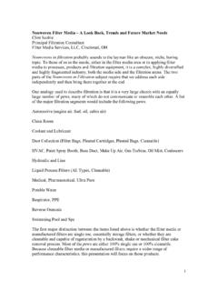
3 The Input Filter on a Switching Power supply has two primary functions. One is to prevent electromagnetic interference, generated by the Switching source from reaching the Power line and affecting other equipment. The second purpose of the Input Filter is to prevent high frequency voltage on the Power line from passing through the output of the Power supply. A passive L-C Filter solution has the characteristic to achieve both filtering requirements. The goal for the Input Filter Design should be to achieve the best compromise between total performance of the Filter with small size and cost. UNDAMPED L-C Filter The first simple passive Filter solution is the undamped L-C passive Filter shown in figure (1).
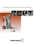
4 Ideally a second order Filter provides 12dB per octave of attenuation after the cutoff frequency f0, it has no gain before f0, and presents a peaking at the resonant frequency f0. 2010 National Semiconductor Corporation f012 LC Figure 1: Undamped LC Filter One of the critical factors involved in designing a second order Filter is the attenuation characteristics at the corner frequency f0. The gain near the cutoff frequency could be very large, and amplify the noise at that frequency. To have a better understanding of the nature of the problem it is necessary to analyze the transfer function of the Filter : The transfer function can be rewritten with the frequency expressed in radians: Ffilter1s()Voutfilters()Vinfilters():==1 1sLRload +LC s2 + :=Cutoff frequency [Hz] (resonance frequencySecond Order Input , HzMagnitude, dB 11= :=Figure 2 : Transfer Function of L-C Filter for differents damping factors 2010 National Semiconductor Corporation Ffilter1 ()11LC 2 j LRload +:==11j2 0 + 2 02 sj := 01LC :=Cutoff frequency in radiant L2R LC :=Damping factor (zeta)The transfer function presents two negative poles at.)
5 0 1 + The damping factor describes the gain at the corner frequency. For >1 the two poles are complex, and the imaginary part gives the peak behavior at the resonant frequency. As the damping factor becomes smaller, the gain at the corner frequency becomes larger, the ideal limit for zero damping would be infinite gain, but the internal resistance of the real components limits the maximum gain. With a damping factor equal to one the imaginary component is null and there is no peaking. A poor damping factor on the Input Filter Design could have other side effects on the final performance of the system. It can influence the transfer function of the feedback control loop, and cause some oscillations at the output of the Power supply.
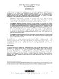
6 The Middlebrook s extra element theorem (paper [2]), explains that the Input Filter does not significantly modify the converter loop gain if the output impedance curve of the Input Filter is far below the Input impedance curve of the converter. In other words to avoid oscillations it is important to keep the peak output impedance of the Filter below the Input impedance of the converter. (See figure 3) From a Design point of view, a good compromise between size of the Filter and performance is obtained with a minimum damping factor of 1/ 2, which provides a 3 dB attenuation at the corner frequency and a favorable control over the stability of the final control system.
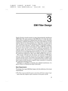
7 2010 National Semiconductor Corporation , HzOhmPower supply Input impedanceFilter output impedanceFigure 3 : Output impedance of the Input Filter , and Input impedance of the Switching Power supply: the two curves should be well separated. PARALLEL DAMPED Filter In most of the cases an undamped second order Filter like that shown in fig. 1 does not easily meet the damping requirements, thus, a damped version is preferred: Figure 4 : Parallel damped Filter Figure 4 shows a damped Filter made with a resistor Rd in series with a capacitor Cd, all connected in parallel with the Filter s capacitor Cf. Figure 4 shows a damped Filter made with a resistor Rd in series with a capacitor Cd, all connected in parallel with the Filter s capacitor Cf.
8 The purpose of resistor Rd is to reduce the output peak impedance of the Filter at the cutoff frequency. The capacitor Cd blocks the dc component of the Input voltage and avoids the Power dissipation on Rd. The purpose of resistor Rd is to reduce the output peak impedance of the Filter at the cutoff frequency. The capacitor Cd blocks the dc component of the Input voltage and avoids the Power dissipation on Rd. The capacitor Cd should have lower impedance than Rd at the resonant frequency and be a bigger value than the Filter capacitor in order not to affect the cutoff point of the main R-L Filter . The capacitor Cd should have lower impedance than Rd at the resonant frequency and be a bigger value than the Filter capacitor in order not to affect the cutoff point of the main R-L Filter .
9 The output impedance of the Filter can be calculated from the parallel of the three block impedancesZ1, Z2, and Z3: The output impedance of the Filter can be calculated from the parallel of the three block impedancesZ1, Z2, and Z3: 2010 National Semiconductor Corporation The transfer function is: Where is Z2 parallel with Z3. The transfer function presents a zero and three poles, where the zero and the first pole fall close to each other at frequency 1/RdCd. The other two dominant poles fall at the cutoff frequency, =1/ LC. Without compromising the results, the first pole and the zero can be ignored and the formula can be approximated to a second order one: (for frequencies higher than 1/RdCd, the term (1+RdCd s) RdCd s ) The approximated formula for the parallel damped Filter is identical to the transfer function of the undamped Filter ; the only difference being the damping factor is calculated with the Rd resistance.
10 It is demonstrated that for a parallel damped Filter the peaking is minimized with a amping factor equal to: bining the last two equations, the optimum damping resistance value Rd is equal Zfilter2s()11Z1s()d Comto: 1Z2s()+1Z3s()+:==sL 1 RdCd s +() s3L C Cd Rd s2L CCd+() +sRd Cd +1+Ffilter2s() + :==1 RdCd s +32s L C Cd Rd s L CCd+() +RdCd s +1+Ffilter2s()11LC Cd+() s2 1 RdCd s +()+LC Cd Rd s3 1 RdCd s +()+:=11LC n 1+() s2 RdC n s +LC Cd Rd s3 RdCd s +=11 LRdn1+()ns +LC s += Where CdnC := 2n1+nL2Rd LC := 2opt2n+()43 +() n2n2 4n+() :=RdoptLCn1+2n 2n2 4n+() 2n+()43n +() :==LCwith n = 4C4C :=d 2010 National Semiconductor Corporation tput impedance and the transfer function of the parallel amped Filter respectively.