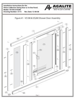
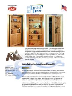
Transcription of Installation - Bradley Corp
1 Box 309, Menomonee Falls, WI USA 53052-0309 PHONE ( ) FAX HDWT-INSTR-012 Rev F; ECN 12-14-015E 2015 BradleyPage 1 of 27 8/13/2015 Powder Coated & Stainless Steel Restroom Partitions Floor-to-Ceiling Series 700 Table of ContentsPre- Installation Information ..2 Layout Dimensions for Brackets ..3 Mounting Brackets to Wall ..4-5 Leveling Bolts to Pilaster ..5 Mounting Brackets to Pilasters ..6-7 Pilaster Mounting Hardware ..7-8 Pilasters and Panels ..9 11 Telescoping and Wall Hung Pilasters ..12-15 Pilaster Shoes ..16 Hinges ..17 20 Door Hardware ..21 24 Urinal Screens ..25 27*HDWT-INSTR-012*For Standard Height Doors and Panels OnlyWARNINGB efore beginning Installation , make sure that the wall and floor backing are adequate to support the secure mounting of the toilet compartment prevent warping, always lay the material flat.
2 Do not lean the material against the wall or stack prevent "dimpling," extra caution should be taken when instructed to drill through one side of face this Installation manual completely to ensure proper Installation , then file it with the owner or maintenance department. This Installation manual provides instruction for the assembly of normal partition configurations and standard components. Non-standard configurations or components including but not limited to curved or angled walls, partial walls, oversized panels, or modified hardware are not covered in this manual. Compliance and conformity to local codes and ordinances is the responsibility of the installer. Separate parts from packaging and make sure all parts are accounted for before discarding packaging material.
3 If any parts are missing, do not begin Installation until you obtain the missing parts. Product warranties and parts information may be found on Bradley 's web site at Coated & Stainless Steel Restroom Partitions, Floor-to-Ceiling Series 700 Installation8/13/2015 Bradley HDWT-INSTR-012 Rev F; ECN 12-14-015 ESupplies Required:Hardware Provided#14-16 Plastic AnchorFAST-T373#14 x 2" Button-Head Sheet Metal Screw Torx-T27 DriveFAST-P002 (Stainless)#10 x 5/8" Button-Head Sheet Metal Screw Torx-T27 DriveFAST-Z0019 Example of Submittal Drawing Chalk line and pencil Tape measure and 4' level Jigsaw (or hacksaw) and circular saw Two spring clamps 1/8",9/64", 3/16" and 1/4" drill bits Power drill or screw gun with drill bit extension 1/4" and 5/16" ceramic tile and masonry drill bit Hammer drill Spacer, 12" (305mm)
4 High and strong enough to support weight of panel#14 x 5/8" Button-Head Sheet Metal Screw Torx-T27 DriveFAST-Z0016#5-40 x 11/16" Flat-Head Sheet Metal Screw Torx-T10 DriveFAST-T3001/4"- 14 x 5/8" Sheet Metal Screw Torx-T27 Drive FAST-S355A#10 x 3/4" Flat-Head Sheet Metal Screw Torx-T25 Drive FAST-Z0006#14 x 2" Button-Head Sheet Metal Screw Torx-T27 DriveFAST-Z002 (Chrome Plated)#10-24 x 3/4" Button-Head Barrel NutTorx-T27 Drive FAST-Z003 (Chrome Plated)#10-24 x 3/4" Button-Head Barrel NutTorx-T27 Drive FAST-P003 (Stainless)#10-24 x 3/4" Button-Head Shoulder Screw Torx-T27 Drive FAST-Z004 (Chrome Plated)#10-24 x 3/4" Button-Head Shoulder Screw Torx-T27 Drive FAST-P004 (Stainless)#10-24 x 1" Button-Head Shoulder Screw Torx-T27 Drive FAST-Z004A (Chrome Plated)#10-24 x 1" Button-Head Shoulder Screw Torx-T27 Drive FAST-P004A (Stainless)#10-24 x 2" Flat-Head Machine Screw Torx-T25 Drive FAST-Z00275/16" - 18 x 3" Leveling Bolt FAST-S003961-1/4" (1556mm) to face60-1/2" (1537mm)wall to centerline36" (914mm)center to center36" (914mm)24" (610mm)26" (660mm)8" (203mm)3" (76mm)1" (25mm) gap1" (25mm) gap1/2" (13mm) gap3"3-1/2" 1-1/2"20-1/2" 6-1/2" 58-1/2" (1486mm)58-1/2" (1486mm)
5 #10 x 2" Flat-Head Sheet Metal Screw Torx-T25 DriveFAST-S0023#10 x 5/8" Button-HeadSheet Metal ScrewTorx-T27 Drive FAST-S351A3 Installation Powder Coated & Stainless Steel Restroom Partitions, Floor-to-Ceiling Series 700 Bradley HDWT-INSTR-012 Rev F; ECN 12-14-015E 8/13/2015**CLCLCLCLCLCLP ilaster plumb lineWhen installing the partition components, consult the applicabale Mills Partition submittal drawing for compartment layout Dimensions - Stirrup Brackets (Standard)Pilaster Centerline: Measure from the back wall forward to the face of the compartment, subtract 5/8" (16mm) and mark this location on the floor ("A") . Mark the same measurement on the opposite end of your layout ("A1") and draw a straight line connecting both marks.
6 For Freestanding (FS) Partitions: Refer to submittal drawings and determine the approximate location of the outside panels . Establish dimensions "A" and "A1" as explained above .APanel Centerline: Measure the stall width across the back wall and place a mark at the base of the rear wall ("B") . Repeat this step for each panel, starting each measurement from the last panel centerline ("B1") .BDraw a plumb line on all walls from each pilaster and panel centerline . From the highest point in the room, measure 18" (457mm) and 64" (1626mm) from the floor and place a mark on the pilaster/panel plumb line . These marks represent the hole center line of the stirrup brackets . Use a level to transfer that mark to all other plumb lines ("C").
7 CPanel plumb lineCLCLCLCL**Pilaster plumb lineWhen installing the partition components, consult the applicable Mills Partition submittal drawing for compartment layout Dimensions - Continuous Brackets (Optional)Pilaster Centerline: Measure from the back wall forward to the face of the compartment, subtract 5/8" (16mm) and mark this location on the floor ("A") . Mark the same measurement on the opposite end of your layout ("A1") and draw a straight line connecting both marks .For Freestanding (FS) Partitions: Refer to submittal drawings and determine the approximate location of the outside panels . Establish dimensions "A" and "A1" as explained above .APanel Centerline: Measure the stall width across the back wall and place a mark at the base of the rear wall ("B").
8 Repeat this step for each panel, starting each measurement from the last panel centerline ("B1") .BDraw a plumb line on all walls from each pilaster and panel centerline . From the highest point in the room, measure from the floor and place a mark on the pilaster/panel plumb line at dimension "C" for the respective bracket type (see table on right) . Use a level to transfer that mark to all other plumb lines ("D") .CPanel plumb line64" (1626mm)18" (457mm)"C""D""C""D""C""C""C""C""B""B""B1 ""B1""A1""A1""A""A""C""D"Dim "C"Stainless Steel12-1/2" (318mm)Aluminum12-1/4" (311mm)4 Powder Coated & Stainless Steel Restroom Partitions, Floor-to-Ceiling Series 700 Installation8/13/2015 Bradley HDWT-INSTR-012 Rev F; ECN 12-14-015E2 Stirrup Brackets to Wall (Standard)established level linepilaster/panel plumb linefloorCLPlace the center of each stirrup bracket at the established level line.
9 Center the bracket opening on the pilaster/panel plumb line .AInsert the plastic anchors in all holes and secure the brackets to the wall with the #14 x 2" screws provided .COn end panel and pilaster applications, position the bracket with the ear facing toward the inside of the the bracket as a template, mark the hole locations on the wall . Remove the bracket and drill a 5/16" hole (min . 2" [51mm] deep) at each hole location .BOne-Eared BracketTwo-Eared BracketPilaster bracket is shown here. 1-1/4" opening brackets are for pilasters and 1" opening brackets are for Stainless Steel Brackets to Wall (Optional)established level linepilaster plumb linefloorCLPlace the bottom of each continuous bracket at the established level line.
10 Center the bracket opening on the pilaster/panel plumb line .AInsert the plastic anchors in all holes and secure the brackets to the wall with the #14 x 2" stainless screws provided .COn pilaster applications, position the bracket with the ear facing toward the inside of the the bracket as a template, mark the hole locations on the wall . Remove the bracket and drill a 5/16" hole (min . 2" [51mm] deep) at each hole location .BBrackets are used as templates, but since the hole patterns may be different, the brackets may not be bracket is shown here; "EAR" brackets are for pilasters and "U" brackets are for panels."Ear" Bracket"U" Bracket5 Installation Powder Coated & Stainless Steel Restroom Partitions, Floor-to-Ceiling Series 700 Bradley HDWT-INSTR-012 Rev F; ECN 12-14-015E 8/13/20152bContinuous Aluminum Brackets to Wall (Optional)established level linepilaster/panel plumb linefloorCLPlace the bottom of each continuous bracket at the established level line.