Transcription of INSTALLATION - directeddealers.com
1 Table of ContentsExperienced security installers may skip to Pg. 8, but read all the italicized sections, as they describe changes and/or new Points to RememberPage 2 Deciding on Component Location3 Finding the Wires you Need5 Step-by-step meter instructions!Making your Wire Connections7 Primary Harness Diagram8 Wire Connection Guide9 Plug in LED and Valet /Program Switch11 Four-pin Shock Sensor Harness11 New Multiplex InputsBypassing Sensor Inputs12 Door Lock Wiring Diagrams12-15 Transmitter/Receiver Learn Routine 16 Two-vehicle Operation with Single Transmitter17 Operating-Settings Learn Routine 18 Feature Descriptions20 Nuisance Prevention Circuitry21 Valet Mode21 Table of Zones22 Vehicle Recovery System(VRS ) Installation22 Troubleshooting23 INSTALLATION GUIDED irected Electronics, + 1995,1997 Directed Electronics, Inc.
2 Vista, not disconnect the battery if the vehicle has an antitheft-coded radio. If equipped with an air bag, avoiddisconnecting the battery if possible. IMPORTANT: Many airbag systems will display a diagnostic code throughtheir warning light after they lose power. Disconnecting the battery requires this code to be erased, a procedurethat can require a trip to the beginning the INSTALLATION : Check with the customer on Status LED location. Remove the domelight fuse. This prevents accidentally draining the battery. Roll down a window to avoid being locked out of the the install: Test all functions. The "Using Your System" section of the Owner's Guide is very helpful when testing. When testing, don t forget that this system is equipped with Nuisance Prevention can bypass trigger zones, making them appear to stop working.
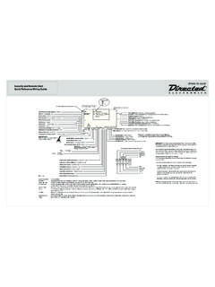
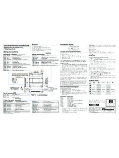
3 (See page 21) INSTALLATION POINTS TO REMEMBERPre-wired 8618 Starter KillRelayPlug-inValet /ProgramswitchPrimaryHarnessH13-pin2-wir edoorlockharnessTwo 491T remotetransmittersPlug-inStatus LEDVRS plug-inswitchRemovable doorfor programmingjumpers504T Plug-inStinger shocksensor514 TRevenger Soft-chirp siren2-pinminiredVRS plug2-pinminiblueValet /Programplug4-pin504 Tshocksensorplug2-pinmicroLEDplug 1995,1997 Directed Electronics, Inc. Vista, One:Deciding on Component LocationsSirenSome things to remember when mounting the siren: Keep it away from heat sources. Radiators, exhaust manifolds, turbochargers, and heat shields are allthings to avoid. Mount it where a thief cannot easily disconnect it, whether the hood is open or shut. Both the siren andits wires should be difficult to find. This usually involves disguising the wire to look like a factory harness.
4 We recommend against grounding the siren to itsmounting screws. Instead, we recommend runningboth the red and black wires into the passengercompartment and grounding to one common point forall devices. After all, both wires are the same lengthand come already bonded together. Wheneverpossible, conceal your wires in the factory harnessesor in the same style loom as the factory. When possible, put the siren on the same side of thevehicle as the control module, where its wires willreach the control module s wires without extendingthem. Always run the wires through the center of agrommet, never through bare metal! Point the siren down so water does not collect in ModuleNever put the control module in the engine compartment!The first step in hot-wiring a vehicle is removing the driver's side underdash panel to access the starter and ignitionwires.
5 If the control module is placed just behind the driver's side dash it can easily be locating the control module, try to find a secure location that will not require you to extend the harnesses wires(they are meters long). Keep it away from the heater core (or anyother heat sources) and any obvious higher the control module is in the vehicle, the better thetransmitter range will be. If you put the control module under a seator inside a metal dashboard, range will suffer, and you may wish toadd a 542T Range Extending Antenna (available separately).Some good control module locations: Above the glove box, inside thecenter console, above the underdash fuse box, above the radio, etc. 1995,1997 Directed Electronics, Inc. Vista, Doubleguard Shock SensorNever put the Stinger in the engine compartment!
6 Find a spot close to the control module so that the wires do not need to be extended. Keep it away from the heatercore (or any other heat sources) and any obvious the Stinger is mounted is the most important factor in its performance. We recommend two mounting methods:Using double-sided tape or hook-and-loop fastener to mount to a trim panel or an air duct, or wire-tying to a wireharness. If mounting the sensor where it cannot be easily reached for adjustment, hook-and-loop fastening tape (suchas Velcro) is recommended for ease of removal for future : In many vehicles, tying the sensor to a steering column or screwing it to metal will result in poorsensitivity, especially on the rear of the Program SwitchEnsure that the location you pick for the switch has sufficient clearance to the rear. The switch should be well should be placed so passengers or stored items (such as in a glove box or center console) cannot accidentally hitit.
7 The switch fits in a 9/32" system has Remote Valet . The user can enter and exit Valet Mode without having to reach the Valet /programswitch. DEI introduced this feature so that switch location was less critical in day-to-day use. As long as theValet /program switch can be reached to disarm without a transmitter, easy access is not ! When the vehicle is delivered, please show the user where the switches are located andhow to disarm the system with LEDT hings to remember when positioning the Status LED: It should be visible from both sides and the rear of the vehicle, if posible. It needs at least 1/2" clearance to the rear. It is easiest to use a small removable panel, such as a switch blank ora dash bezel. Remove it before drilling your 9/32" hole. Use quick-disconnects near the LED wires if the panel is lets mechanics or other installers remove the panel without cuttingthe wires.
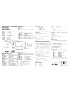
8 1995,1997 Directed Electronics, Inc. Vista, Starter Kill RelayIf Starter Kill Relay or its connections are immediately visible upon removal of the underdash panel, they can easilybe bypassed. Always make the relay and its connections difficult to discern from the factory wiring! Exposed yellowbutt connectors do not look like factory parts, and will not fool anyone! For this reason, routing the starter kill wiresaway from the steering column is 2:Finding the Wires You NeedNow that you have decided where each component will be located, you re going to find the wires in the car that thesecurity system will be connected ! Do not use a 12V test light to find these wires! All testing described in this manual is describedusing a digital Constant 12 VWe recommend two possible sources for 12V constant: The (+) terminal of the battery, or the constant supply to theignition switch.
9 Always install a fuse within 12 inches of this connection. If the fuse also will be powering othercircuits, such as door locks, a power window module, a Nite-Lite headlight control system, etc.; fuse ! Do not remove the fuse holder on the red wire. It ensures that the control module has its ownfuse, of the proper value, regardless of how many accessories are added to the main power the 12V Switched Ignition WireThe ignition wire is powered when the key is in the run or start position. This is because the ignition wire powers theignition system (spark plugs, coil) as well as the fuel delivery system (fuel pump, fuel injection computer). Accessorywires, on the other hand, lose power when the key is in the start position to make more current available to the to find (+)12V ignition with your multimeter:1. Set to DCV or DC voltage (12V or 20V is fine).
10 2. Attach the (-) probe of the meter to chassis Probe the wire you suspect of being the ignition wire. The steering columnharness or ignition switch harness is an excellent place to find this Turn the ignition key switch to the run position. If your meter reads (+)12V,go to the next step. If it doesn t, probe another Now turn the key to the start position. The meter display should stay steady,not dropping by more than a few tenths of a volt. If it drops close to or allthe way to zero, go back to step 3. If it stays steady at (+)12V, you havefound an ignition wire. 1995,1997 Directed Electronics, Inc. Vista, a (+) Parking Iight WireThe (+) parking light wire is often found near the switch. Many cars have the switch built into the turn signal lever, andin these cars the parking light wire can be found in the steering column.