Transcription of Installation Guide
1 This product is intended for Installation by a professional installer only! Attempts to install this product by a per-son other than a trained professional may result in severe damage to a vehicle s electrical system and components. 2012 Directed. Vista, CA N4103 2012 01 Installation GuideKeyless Entry Remote Start4103, 4-button seriesBitwriters with a date code of 6a or older require an IC upgrade (p/n 998M). Some Bitwriters with a date code of 6B do not require the IC upgrade, refer to tech tip # 1112 for more information. Bitwriter , Code Hopping , Doubleguard , ESP , Fail-Safe , Ghost Switch , Learn Routine , Nite-Lite , Nuisance Prevention Circuitry, Revenger , Silent Mode , Soft Chirp , Stinger , Valet , Vehicle Recovery System , VRS , and Warn Away are all Trademarks or Registered Trademarks of Direct-ed Bitwriter (p/n 998U) requires chip version or newer to program this ! Safety first ..4 Wiring diagram.
2 5 Wiring connections ..5 Main Harness (H1), 9-pin connector ..5 Door Lock - 3 pin connector ..6 Heavy Gauge Relay (H2), 6-pin connector ..6 Satellite harness - 4-pin connector ..6 Remote Start harness (H3) 5-pin connector ..6 Tach Learning ..7 Virtual Tach ..7 Neutral safety switch interface ..8 Testing the neutral safety switch ..8 Remote start shutdown diagnostics ..9 Remote programming ..9 Programming system features ..10 Feature menus ..11 Menu 1 ..11 Menu 2 ..13 Red 4-pin port, Bitwriter/ESP2 or D2D programming ..14 Bitwriter only options ..15 Bitwriter feature descriptions ..15 Basic remote functions ..16 Reset and deletion ..17 Troubleshooting: Keyless entry ..17 Troubleshooting: Remote start ..174 2012 Directed. All rights ! Safety firstThe following safety warnings must be observed at all times: Due to the complexity of this system, Installation of this product must only be performed by an authorized Directed Electronics dealer. When properly installed, this system can start the vehicle via a command signal from the remote control.
3 Therefore, never operate the system in an area that does not have adequate ventilation. The following precautions are the sole responsibility of the user; however, authorized Directed Electronics dealers should: Never use a test light or logic probe when installing this unit. Always use a multimeter. Never operate the system in an enclosed or partially enclosed area without ventilation (such as a garage). When parking in an enclosed or partially enclosed area or when having the vehicle serviced, the remote start system must be disabled using the installed toggle switch. It is the user s sole responsibility to prop-erly handle and keep out of reach from children all remote controls to assure that the system does not unintentionally remote start the MUST INSTALL A CARBON MONOXIDE DETECTOR IN OR ABOUT THE LIVING AREA ADJACENT TO THE VEHICLE. ALL DOORS LEADING FROM ADJACENT LIVING AREAS TO THE ENCLOSED OR PARTIALLY ENCLOSED VEHICLE STORAGE AREA MUST REMAIN CLOSED AT ALL of this product in a manner contrary to its intended mode of operation may result in property damage, personal injury, or death.
4 Except when performing the Safety Check outlined in this Installation Guide , (1) Never remotely start the vehicle with the vehicle in gear, and (2) Never remotely start the vehicle with the keys in the ignition. The user is responsible for having the neutral safety feature of the vehicle periodically checked, wherein the vehicle must not remotely start while the car is in gear. This testing should be performed by an authorized Directed Electronics dealer in accordance with the Safety Check outlined in this product Installation Guide . If the vehicle starts in gear, cease remote start operation immediately and consult with the user to fix the problem immediately. After the remote start module has been installed, test the remote start module in accordance with the Safety Check outlined in this Installation Guide . If the vehicle starts when performing the Neutral Safety Shutdown Circuit test, the remote start unit has not been properly installed. The remote start module must be removed or properly reinstalled so that the vehicle does not start in gear.
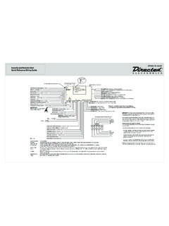
5 All installations must be performed by an authorized Directed Electronics dealer. OPERATION OF THE REMOTE START MODULE IF THE VEHICLE STARTS IN GEAR IS CONTRARY TO ITS IN-TENDED MODE OF OPERATION. OPERATING THE REMOTE START SYSTEM UNDER THESE CONDITIONS MAY RESULT IN PROPERTY DAMAGE OR PERSONAL INJURY. IMMEDIATELY CEASE THE USE OF THE UNIT AND REPAIR OR DISCONNECT THE INSTALLED REMOTE START MODULE. DIRECTED ELECTRONICS WILL NOT BE HELD RESPONSIBLE OR PAY FOR Installation OR REINSTALLATION ! This product is designed for fuel-injected, automatic transmission vehicles only. Installing it in a standard transmission vehicle is dangerous and is contrary to its intended 2012 Directed. All rights diagramControl Button(Valet Switch)Door Lock/unlockHarnessSide ViewAntennaAntennaLED (Programmingindicator)Parking light jumpersPrimary HarnessRemote Start HarnessHeavyGaugeRelaySide ViewSatellite HarnessRed 4-pin port, Bitwriter/ ESP2 or D2D 4x03 Wiring connectionsMain Harness (H1), 9-pin connectorH1/1 LIGHT GREEN BLACK(-) 200mA FACTORY ALARM DISARMH1/2 GREEN/WHITE(-) 200mA FACTORY ALARM REARMH1/3 YELLOW(+) IGNITION OUT (TO ALARM) H1/4 WHITE/BLUE(-) ACTIVATION INPUT H1/5 ORANGE(-) 500mA GROUND WHEN LOCKED/ANTI-GRIND OUTPUTH1/6 BROWN(-) 200mA HORN OUTPUTH1/7 RED/WHITE(-) 200mA TRUNK RELEASE OUTPUTH1/8 BLACKGROUNDH1/9 WHITE(+/-) LIGHT FLASH OUTPUT6 2012 Directed.
6 All rights Lock - 3 pin connector1 LIGHT BLUE(-) UNLOCK 2 EMPTYNOT USED3 GREEN (-) LOCK Heavy Gauge Relay (H2), 6-pin connectorH2/1 PINKOUTPUT TO PRIMARY IGNITION CIRCUIT H2/2 PURPLEOUTPUT TO starter CIRCUIT H2/3 ORANGEOUTPUT TO ACCESSORY CIRCUITH2/4 RED(+) 30A HIGH CURRENT 12V INPUT H2/5 PINK/WHITEOUTPUT TO SECOND IGNITION/ACCESSORY CIRCUITH2/6 RED(+) 30A HIGH CURRENT 12V INPUTS atellite harness - 4-pin connector1 BLUE(-) 200mA STATUS OUTPUT2 ORANGE(-) 200mA ACCESSORY OUTPUT3 PURPLE(-) 200mA starter OUTPUT4 PINK(-) 200mA IGNITION OUTPUTR emote Start harness (H3) 5-pin connectorH3/1 BLACK/WHITE(-) NEUTRAL SAFETY SWITCH INPUTH3/2 VIOLET/WHITETACHOMETER INPUT WIREH3/3 BROWN (+) BRAKE SHUTDOWN INPUT WIREH3/4 GRAY(-) HOOD PIN SWITCH SHUTDOWN WIREH3/5 BLUE/WHITE(-) 200 mA 2ND STATUS/REAR DEFOGGER7 2012 Directed. All rights LearningTo learn the tach signal:1. Start the vehicle with the Within 5 seconds, press and hold the Valet (Control) After 3 seconds the system LED will light constant when the tach signal is Release the Valet (Control) : This unit can learn the tachometer with the analog input or through D2D using an interface module.
7 The unit con-firms which source is used. When programming tach learning with: Analog, the parking lights flash one time D2D inerface module, the parking lights flash twiceIf the tachometer input on the system is connected to the vehicle, the D2D tachometer input will be TachNote: Virtual tach is not recommended for diesel program Virtual Tach:1. After the install is complete, remote start the car. 2. If the car does not start on the first attempt, let the remote start attempt Once the car starts, let it run until the parking lights come When the parking lights come on, shut off the remote start with the remote - that s it! Virtual Tach is Tach handles disengaging the starter motor during remote starting it does not address over-rev. If the customer wants to have the over-rev protection capability, the tach wire must be connected. This may involve more Installation shop charges than initially : If the Virtual Tach mode over cranks or doesn't crank the vehicle long enough to start and run the car, use the Bitwriter to add or subtract the starter output time.
8 You can adjust the output time in incre-ments of 50msec of the learned time using the Bitwriter. 8 2012 Directed. All rights safety switch interfaceSome vehicles do not have an electrical neutral safety switch, but instead have a mechanical neutral safety switch that interrupts the starter wire when the vehicle is in any drive gear. The remote start must be interfaced before the neutral safety switch , to provide protection from starting in gear. However, some vehicles combine the column shift and the neutral safety switch into one mechanical part, and in this case you will not be able to interface the remote start before the neutral safety switch. Important: You must complete the remote start system Installation before doing the follow-ing test. Ensure that the remote start system is functioning normally. This includes connect-ing to the brake as a the neutral safety switch1. Make sure there is adequate clearance to the front and rear of the vehicle because it may move Make sure the hood is closed and there are no remote start shut-downs Set the emergency Turn the key to the run position, this releases the Place the car in drive (D).
9 6. Place your foot directly over the brake pedal, but do not depress it. Be ready to step on the brake if the starter Activate the remote start If the starter engages, immediately depress the brake to shut the remote start system down. If the starter does not engage, no additional safety system is required. If the starter engages and the vehicle is a General Motors product or Dodge Dakota pickup, refer to for Document 1008 under the Resource tab. For an alternative shut-down method which prevents the starter from engaging. If the vehicle is not a General Motors product or a Dodge Dakota pickup, please call Directed Electronics Technical Support for an alternative shut-down method. Do not return the vehicle to the customer until this feature is properly installed!9 2012 Directed. All rights start shutdown diagnosticsIf the remote start activates but fails to stay running, the remote start module has the ability to inform you of what may have caused the remote start failure.
10 Before performing shutdown diagnostics it is important that you let the remote start shut off on its own let it attempt to start 3 times then shut down, if this is not done the unit will report the shutdown you used to shut off the remote : Shutdown diagnostics does not report if the vehicles factory immobilizer is causing the perform shutdown diagnostics:1. With the ignition Off, press and hold the Valet button 2. Tu r n the ignition On and then back Off while holding the Valet Release the Valet Press and release the Valet button. The status LED flashes to report the last shutdown for one minute or until the ignition is turned on, as shown in the following table:Status LED Flashes Shutdown Mode1 flash Runtime expired 2 flashes Over-rev shutdown 3 flashes Low or no RPM4 flashes Transmitter shutdown (or optional push button)5 flashes (-) Hood shutdown (H3/4 GRAY)6 flashes (+) Shutdown (H3/3 BROWN)7 flashes Neutral safety shutdown (H3/1 BLACK/WHITE)8 flashes Wait-to-start timed outRemote programming1.