Transcription of Installation Guide - directeddealers.com
1 2004 directed Electronics, Inc. Vista, CA N426V 07-04 NOTE:This product is intended for Installation by a professional installer only!Any attempt to install this product by any person other than a trained professionalmay result in severe damage to a vehicle s electrical system and GGuuiiddeeBitwriter , Code Hopping , , Doubleguard , ESP , FailSafe , Ghost Switch , LearnRoutine , Nite-Lite , Nuisance Prevention Circuitry, NPC , Revenger , Silent Mode , SoftChirp , Stinger , Valet , Vehicle Recovery System , VRS , and Warn Away are all Trademarks orRegistered Trademarks of directed Electronics, Bitwriter (p/n 998T)requires chip version ornewer to program this 880000--999999--11332299 TTeecchhnniiccaall SSuuppppoorrtt 880000--775533--00880000 These resources are for authorized directed Dealer use only.
2 2002 directed Electronics, of ContentsPPrriimmaarryy HHaarrnneessss ((HH11)) WWiirree CCoonnnneeccttiioonn GGuuiiddee ..44 Primary Harness Wiring Diagram ..4 Primary Harness Wiring Instructions ..4 DDoooorr LLoocckk HHaarrnneessss ((HH22)),, 33--PPIINN CCoonnnneeccttoorr ..1100 PPeerriipphheerraall PPlluugg--IInn HHaarrnneesssseess ..1100 Super Bright LED, 2-Pin WHITE Plug ..10 Valet/Program Switch, 2-Pin BLUE Plug ..11 Programmer Interface, 3-Pin BLACK Plug ..11 Mounting the Receiver/Antenna ..11 OOnn--BBooaarrdd DDuuaall--SSttaaggee SShhoocckk SSeennssoorr ..1122 OOppttiioonnaall SSeennssoorr HHaarrnneessss,, 44--ppiinn CCoonnnneeccttoorr ..1133 PPrrooggrraammmmiinngg JJuummppeerr ..1133 Light Flash Jumper.
3 13 BByyppaassssiinngg SSeennssoorr IInnppuuttss ..1144 SSyysstteemm FFeeaattuurreess LLeeaarrnn RRoouuttiinnee ..1144 SSyysstteemm FFeeaattuurreess MMeennuuss ..1177 Menu #1 - Basic Features ..17 Menu #2 - Advanced Features ..17 FFeeaattuurree DDeessccrriippttiioonnss ..1188 Menu #1 - Basic Features ..18 Menu #2 - Advanced Features ..19 TTrraannssmmiitttteerr//RReecceeiivveerr LLeeaarrnn RRoouuttiinnee ..2211 TTrraannssmmiitttteerr CCoonnffiigguurraattiioonnss ..2233 Standard Configuration ..23 Expanded Configuration ..23 DDiiaaggnnoossttiiccss ..2244 Arm/Disarm Diagnostics ..24 System Status Chips ..24 Table of Zones ..24 LLoonngg TTeerrmm EEvveenntt HHiissttoorryy ..2255 MMuullttii--LLeevveell SSeeccuurriittyy AArrmmiinngg.
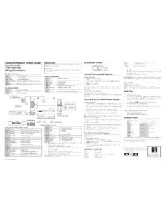
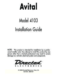
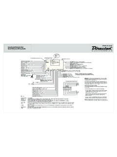
4 2255 OOppttiioonnaall VVeehhiiccllee RReeccoovveerryy SSyysstteemm ((VVRRSS)) ..2266 NNuuiissaannccee PPrreevveennttiioonn CCiirrccuuiittrryy ..2266 RRaappiidd RReessuummee LLooggiicc ..2266 TTrroouubblleesshhoooottiinngg ..2277 WWiirriinngg QQuuiicckk RReeffeerreennccee 2002 directed Electronics, Harness (H1) Wire Connection GuidePrimary Harness Wiring Diagram_____Primary Harness Wiring InstructionsThis Guide describes in detail the connection of each wire. Also included are possible applicationsof each wire. This system was designed with the ultimate in flexibility and security in mind. Manyof the wires have more than one possible function. Please read carefully to ensure a thorough under-standing of this ORANGE (-) ground-when-armed outputThis wire supplies a (-) ground as long as the system is armed.
5 This output ceases as soon as thesystem is disarmed. The orange wire is pre-wired to control the 8618 starter kill relay. It can supplyup to 500 mA of : If using the H1/1 ORANGE wire to activate an add-on accessory such as windowautomation, pager or voice module a 1 Amp diode must be installed to ensure proper the diode as shown in the following (-) 200 mA Channel 2 OutputRED(+) Constant Power InputBROWN(+) Siren Output YELLOW(+) Switched Ignition Input, Zone 5 BLACK (-) Chassis Ground Input VIOLET (+) Door Trigger Input, Zone 3 BLUE(-) Instant Trigger Input, Zone 1 GREEN(-) Door Trigger Input, Zone 3 BLACK/WHITE(-) 200 mA Domelight Supervision Output WHITE/BLUE(-) 200 mA Channel 3 Programmable OutputWHITE(+)/(-) Selectable Light Flash OutputORANGE(-)
6 500 mA Armed Output H1/1H1/2H1/3H1/4H1/5H1/6H1/7H1/8H1/9H1/1 0H1/11H1/12 2002 directed Electronics, WHITE (+/-) light flash outputAs shipped, the H1/2 WHITE wire should be connected to the (+) parking light wire. If the light flashpolarity jumper is moved to the (-) position (see the Programming Jumpersection of this installationguide), this wire supplies a (-) 200 mA output. This is suitable for driving (-) light control wires inToyota, Lexus, BMW, some Mitsubishi, some Mazda, and other : For parking light systems that draw 10 amps or more, the jumper must be switched to a(-) light flash output (see the Programming Jumperssection of this Guide ). P/N 8617 or a standardautomotive SPDT relay must be used on the H1/2 light flash output !DO NOT connect this wire to a negative vehicle light flash wire beforechanging the programming jumper to the negative polarity position or damage tovehicle light circuit may !
7 Never interrupt any wire other than the starter 2002 directed Electronics, WHITE/BLUE 200 mA (-) channel 3 outputThis wire provides a (-) 200 mA output whenever the transmitter button(s) controlling channelthree is pressed. This output can be programmed to provide the following types of output (seeSystem Features Learn Routinesection of this Guide ): A vvaalliiddiittyyoutput will send a signal as long as the transmission is received. A llaattcchheeddoutput will send a signal continuously when the channel three button(s) is pressed andreleased. The signal will continue until channel three is pressed again. A llaattcchheedd//rreesseett wwiitthh iiggnniittiioonnoutput works similar to the latched output, but will also reset(output will stop) when the ignition is turned on and then off.
8 A 3300 sseeccoonndd ttiimmeedd output will send a signal for 30 seconds when channel three is pressed. Thisoutput can be shut off during the 30-second period by pressing Channel 3 again. This output can also be programmed to provide a sseeccoonndd uunnlloocckk ppuullsseewhen the unlock buttonis pressed a second time after disarming the system. This can be used to unlock the passengerdoors when installing progressive door BLACK/WHITE (-) 200 mA domelight supervision outputConnect the H1/4 wire to the optional domelight supervision relay as shown in the followingdiagram:IMPORTANT!This output is only intended to drive a relay. It cannot be connecteddirectly to the domelight circuit, as the output cannot support the current draw of oneor more !
9 Never use this wire to drive anything but a relay or a low-current input!This transistorized output can only supply 200 mA, and connecting directly to asolenoid, motor, or other high-current device will cause the module to fail. 2002 directed Electronics, GREEN (-) door trigger inputMost vehicles use negative door trigger circuits. Connect the green wire to a wire showing groundwhen any door is opened. When connecting to newer model vehicles there is generally a need to useindividual door triggers. See DirectFax document 1076 for wiring instructions. This wire will reportZone : If using a door trigger wire that has a delay, Advanced Menu 2, feature 6 or the 998 TBitwriter can be used to turn Bypass Notification BLUE (-) instant trigger inputThis input will respond to a negative input with an instant trigger.
10 It is ideal for hood and trunk pinsand will report on Zone 1. It can also be used with directed single-stage sensors. The H1/6 blueinstant trigger wire can also be used to shunt sensors during operation of auxiliary channels or remotestart. (See Bypassing Sensor Inputssection of this Guide .)H1/7 VIOLET (+) door trigger inputThis type of dome circuit is used in many Ford products. Connect the violet wire to a wire that shows(+)12V when any door is opened. This wire will report Zone : If using a door trigger wire that has a delay, Advanced Menu 2, feature 6 or the 998 TBitwriter can be used to turn Bypass Notification 2002 directed Electronics, BLACK (-) chassis ground connectionConnect this wire to a clean, paint-free sheet metal location (driver kick panel) using a factory boltthat DOES NOT have any vehicle component grounds attached to it.