Transcription of INSTALLATION INSTRUCTIONS
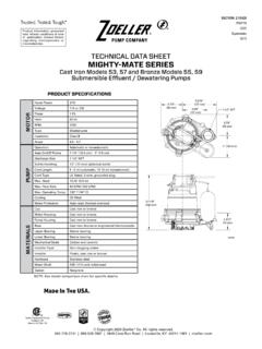
1 1 INSTALLATION INSTRUCTIONSRECOMMENDED MODELSP/N 151797 Notice to installing contractor: INSTRUCTIONS must remain with CHECKLIST - ALL INSTALLATIONSDATE INSTALLED:MODEL NUMBER:1. Inspect your pump. Occasionally, products are damaged during shipment. If the unit is damaged, contact your dealer before using. DO NOT remove the test plugs in the cover nor the motor Carefully read the literature provided to familiarize yourself with specific details regarding INSTALLATION and use. These materials should be retained for future */SUMP/DEWATERINGSEWAGE53 / 57 Series, 98 Series264 Series137 Series, 151 / 152 / 153 Series266 / 267 SeriesCAUTIONSEE BELOW FORLIST OF CAUTIONSSEE BELOW FORLIST OF WARNINGS 1. Make certain that the receptacle is within the reach of the pump s power supply cord. DO NOT USE AN EXTENSION CORD. Extension cords that are too long or too light do not deliver sufficient voltage to the pump motor, and they could present a safety hazard if the insulation were to become damaged or the connection end were to fall into a wet or damp area.
2 2. Make sure the pump electrical supply circuit is equipped with fuses or circuit breakers of proper capacity. A separate branch circuit is recommended, sized according to the National Electrical Code for the current shown on the pump nameplate. 3. Testing for ground. As a safety measure, each electrical outlet should be checked for ground using an Underwriters Laboratory Listed circuit analyzer which will indicate if the power, neutral and ground wires are correctly connected to your outlet. If they are not, call a qualified, licensed electrician. 4. For Added Safety. Pumping and other equipment with a 3-prong grounded plug must be connected to a 3-prong grounded receptacle. For added safety the receptacle may be protected with a ground-fault circuit interrupter. When a pump needs to be connected in a watertight junction box, the plug can be removed and spliced to the supply cable with proper grounding. For added safety this circuit may be protected by a ground-fault circuit interrupter.
3 The complete INSTALLATION must comply with the National Electrical Code and all applicable local codes and ordinances. 5. FOR YOUR PROTECTION, ALWAYS DISCONNECT PUMP FROM ITS POWER SOURCE BEFORE HANDLING. Single phase pumps are supplied with a 3-prong grounded plug to help protect you against the possibility of electrical shock. DO NOT, UNDER ANY CIRCUMSTANCES, REMOVE THE GROUND PIN. The 3-prong plug must be inserted into a mating 3-prong grounded receptacle. If the INSTALLATION does not have such a receptacle, it must be changed to the proper type, wired and grounded in accordance with the National Electrical Code and all applicable local codes and ordinances. Three phase pumps require motor starting devices with motor overload protection. See FM0486 for duplex installations. 6. The tank is to be vented in accordance with local plumbing code. Pumps must be installed in accordance with the National Electrical Code and all applicable local codes and ordinances.
4 Pumps are not to be installed in locations classified as hazardous in accordance with National Electrical Code, ANSI/NFPA 70. 7. Risk of electrical shock. Do not remove power supply cord and strain relief or connect conduit directly to the pump. 8. INSTALLATION and servicing of electrical circuits and hardware should be performed by a qualified licensed electrician. 9. Pump INSTALLATION and servicing should be performed by a qualified person. 10. Risk of electrical shock - These pumps have not been investigated for use in swimming pool and marine areas. 11. Prop65 Warning for California residents: Cancer and Reproductive Harm- 1. Check to be sure your power source is capable of handling the voltage requirements of the motor, as indicated on the pump name plate. 2. The INSTALLATION of automatic pumps with variable level float switches or nonautomatic pumps using auxiliary variable level float switches is the responsibility of the installing party and care should be taken that the tethered float switch will not hang up on the pump apparatus or pit peculiarities and is secured so that the pump will shut off.
5 It is recommended to use rigid piping and fittings and the pit be 18" (46 cm) or larger in diameter. 3. Information - vent hole purpose. It is necessary that all submersible sump, effluent, and sewage pumps capable of handling various sizes of solid waste be of the bottom intake design to reduce clogging and seal failures. If a check valve is incorporated in the INSTALLATION , a vent hole (approx. 3/16" [5 mm]) must be drilled in the discharge pipe below the check valve and pit cover to purge the unit of trapped air. Trapped air is caused by agitation and/or a dry basin. Vent hole should be checked periodically for clogging. The 53 / 57, and 98 Series pumps have a vent located in the pump housing opposite the float, adjacent to a housing lug, but an additional vent hole is recommended. The vent hole on a High Head application may cause too much turbulence. You may not want to drill one. If you choose not to drill a vent hole, be sure the pump case and impeller is covered with liquid before connecting the pipe to the check valve and no inlet carries air to the pump intake.
6 NOTE: THE HOLE MUST ALSO BE BELOW THE BASIN COVER AND CLEANED PERIODICALLY. Water stream will be visible from this hole during pump run periods. 4. Pump should be checked frequently for debris and/or buildup which may interfere with the float on or off position. Repair and service should be performed by Zoeller Pump Company Authorized Service and Warranty Center. 5. dewatering and effluent sump pumps are not designed for use in pits handling raw sewage. 6. Maximum operating temperature for standard model pumps must not exceed 130 F (54 C). 7. Pump models 266, 267, and 137 must be operated in an upright position. Do not attempt to start pump when tilted or laying on its side. 8. Do not operate a pump in an application where the Total Dynamic Head is less than the minimum Total Dynamic Head listed on the Pump Performance TO WARRANTY ON PAGE : Pumps with the UL mark and pumps with the US mark are tested to UL Standard UL778.
7 CSA Certified pumps are certified to CSA Standard No. information presented here reflects conditions at time of publication. Consult factory regarding discrepancies or TO: BOX 16347 Louisville, KY 40256-0347 SHIP TO: 3649 Cane Run Road Louisville, KY 40211-1961 TEL: (502) 778-2731 1 (800) 928-PUMP FAX: (502) 774-3624 Visit our web * Effluent systems should specify that pumps should not handle solids exceeding 3/4 ( mm) in order to prevent large solids from entering leeching fields, mound systems, etc. (Model 49 Series has 3/8 [ mm] solids capability. 50, 90, and 151 Series have 1/2 [ mm], 130 Series has 5/8 [ mm], 152 and 153 models have 3/4 [ mm].) Where code permits, sewage pumps can be used for effluent systems. Nonautomatic pumps with external-level controls are recommended for septic tank effluent : VENT HOLE FORCHECK VALVESEE #3 IN CAUTION SECTIONBELOW AND #4 ON PAGE 3 Copyright 2019 Zoeller Co. All rights your Zoeller Pump Company Product on our website: Copyright 2019 Zoeller Co.
8 All rights lieu of all other warranties expressed or implied; and we do not authorize any representative or other person to assume for us any other liability in connection with our Manufacturer at, 3649 Cane Run Road, Louisville, Kentucky 40211, Attention: Customer Service Department to obtain any needed repair or replacement of part(s) or additional information pertaining to our EXPRESSLY DISCLAIMS LIABILITY FOR SPECIAL, CONSEQUENTIAL OR INCIDENTAL DAMAGES OR BREACH OF EXPRESSED OR IMPLIED WARRANTY; AND ANY IMPLIED WARRANTY OF FITNESS FOR A PARTICULAR PURPOSE AND OF MERCHANTABILITY SHALL BE LIMITED TO THE DURATION OF THE EXPRESSED states do not allow limitations on the duration of an implied warranty, so the above limitation may not apply to you. Some states do not allow the exclusion or limitation of incidental or consequential damages, so the above limitation or exclusion may not apply to warranty gives you specific legal rights and you may also have other rights which vary from state to WarrantyManufacturer warrants, to the purchaser and subsequent owner during the warranty period, every new product to be free from defects in material and workmanship under normal use and service, when properly used and maintained, for a period of three years from the date of purchase.
9 Proof of purchase is required. Parts that fail within the warranty period, that inspections determine to be defective in material or workmanship, will be repaired, replaced or remanufactured at Manufacturer's option, provided however, that by so doing we will not be obligated to replace an entire assembly, the entire mechanism or the complete unit. No allowance will be made for shipping charges, damages, labor or other charges that may occur due to product failure, repair or warranty does not apply to and there shall be no warranty for any material or product that has been disassembled without prior approval of Manufacturer, subjected to misuse, misapplication, neglect, alteration, accident or act of nature; that has not been installed, operated or maintained in accordance with Manufacturer's INSTALLATION INSTRUCTIONS ; that has been exposed to outside substances including but not limited to the following: sand, gravel, cement, mud, tar, hydrocarbons, hydrocarbon derivatives (oil, gasoline, solvents, etc.)
10 , or other abrasive or corrosive substances, wash towels or feminine sanitary products, etc. in all pumping applications. The warranty set out in the paragraph above is ELECTRICAL PRECAUTIONS- Before servicing a pump, always shut off the main power breaker and then unplug the pump - making sure you are wearing insulated protective sole shoes and not standing in water. Under flooded conditions, contact your local electric company or a qualified licensed electrician for disconnecting electrical service prior to pump removal. Submersible pumps contain oils which becomes pressurized and hot under operating conditions. Allow 2-1/2 hours after disconnecting before attempting the above checklist does not uncover the problem, consult the factory. Do not attempt to service or otherwise disassemble pump. Service must be performed by Zoeller Authorized Service and Warranty Centers. Go to to find the Authorized Service Center in your CHECKLISTEASY DO S & DON'T S FOR INSTALLING A SUMP PUMP 1.