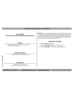
Transcription of INSTALLATION INSTRUCTIONS FOR PART 99-3014G
1 INSTALLATION INSTRUCTIONS FOR PART 99- 3014g . Chevrolet Silverado 1500/GMC Sierra 1500 2014-up Chevrolet Silverado 2500/3500 2015-up Table of Contents GMC Sierra 2500/3500 2015-up Dash 2. Kit Assembly 99- 3014g . ISO DIN radio provision with 3.. Double DIN radio 4. KIT FEATURES. ISO DIN radio provision with pocket Double DIN radio provision Painted gunmetal gray KIT COMPONENTS TOOLS REQUIRED. A) Radio trim panel B) Radio brackets C) Pocket D) (8) #8 x 3/8 truss-head Phillips screws Panel removal tool Phillips screwdriver A B C D Socket wrench Cutting tools (like a Dremel). REV. 4/23/2015 INST99- 3014g . CAUTION: Metra recommends disconnecting the negative battery terminal before beginning any INSTALLATION . All accessories, switches, and especially air bag indicator lights must be plugged in before WIRING & ANTENNA CONNECTIONS (sold separately) reconnecting the battery or cycling the ignition.
2 Wiring Harness: GMOS-LAN-09 GMOS-MOST-01 LC-GMRC-LAN-09 AX-LCD NOTE: Refer to the INSTRUCTIONS included with the Antenna Adapter: 40-EU55 aftermarket radio. METRA. The World's best kits. 1-800-221-0932 COPYRIGHT 2015 METRA ELECTRONICS CORPORATION. 99- 3014g . Dash Disassembly 1. Unclip and remove the trim panel surrounding the radio/climate control panel. (Figure A). 2. Remove (4) 9/32 screws securing the radio/climate control panel. (Figure B). 3. Unclip and remove the factory climate controls 4. Remove (2) 9/32 screws securing the CD player then unplug and remove the player. (Figure C) (Figure A). 5. Unclip and slide out the Onstar module and the tuner box then unplug and remove them. Note: The Onstar module will need to be returned to the sub dash in a lower position from (Figure C).
3 Factory. (Figure C). Continue to kit assembly (Figure B). 2. 99- 3014g . Kit Assembly 1. Cut and remove the specified areas in the sub dash. (Figures A, B). Continued on next page (Figure A) (Figure B). 3. 99- 3014g . Kit Assembly ISO DIN radio provision 1. Mount the pocket to the radio brackets with the (4) #8 x 3/8 . Phillips screws supplied. (Figure A). 2. Mount the bracket/pocket assembly to the radio trim panel with the (4) #8 x 3/8 Phillips screws supplied. (Figure B). 3. Slide the radio into radio brackets and secure with screws supplied with the radio. (Figure C). 4. Clip factory climate controls into the radio trim panel (Figure A) (Figure B) (Figure C). 5. Locate the factory wiring harness and antenna plug in the dash. Metra recommends using the proper mating adapters from Metra and/or AXXESS.
4 6. Reassemble the dash in reverse order of disassembly. 4. 99- 3014g . Kit Assembly Double DIN radio provision 1. Attach the brackets to the radio trim panel using the (4) #8 x 3/8 . screws supplied. (Figure A). 2. Slide the radio into the bracket/. radio housing assembly and secure to the assembly using the screws supplied with the radio. (Figure B). 3. Clip factory climate controls into the radio trim panel 4. Locate the factory wiring harness in the dash. Metra recommends using the proper mating adapter from Metra or AXXESS. Re-connect (Figure A) (Figure B). the negative battery terminal and test the unit for proper operation. 5. Reassemble the dash in reverse order of disassembly. 5. 99- 3014g . 6. 99- 3014g . 7. INSTALLATION INSTRUCTIONS FOR PART 99- 3014g .
5 KNOWLEDGE IS POWER. Enhance your INSTALLATION and fabrication skills by enrolling in the most recognized and respected REV. 4/23/2015 INST99- 3014g . mobile electronics school in our industry. Log onto or call 800-354-6782 for more information and take steps toward a better tomorrow. Metra recommends MECP. certified technicians METRA. The World's best kits. 1-800-221-0932 COPYRIGHT 2015 METRA ELECTRONICS CORPORATION. INSTRUCCIONES DE INSTALACI N PARA LA PIEZA 99- 3014g . Chevrolet Silverado 1500/GMC Sierra 1500 2014 y mas Chevrolet Silverado 2500/3500 2015 y mas Indice GMC Sierra 2500/3500 2015 y mas Desmontaje del 2. 99- 3014g Ensamble del kit . Provisi n de radio ISO DIN con 3.. Provisi n de radio doble 4. Caracter sticas del kit Provisi n de radio ISO DIN con cavidad Provisi n de radio doble DIN.
6 Pintura en gris bronce de ca n Componentes del kit Herramientas requeridas A) Panel de moldura para radio B) Soportes para radio C) Cavidad D) (8) Tornillos Phillips de cabeza Herramienta para quitar paneles segmentada #8 x 3/8 Destornillador Phillips Llave de tubo A B C D Herramientas de corte (como un Dremel). REV. 4/23/2015 INST99- 3014g . PRECAUCI N: Metra recomienda desconectar el terminal negativo de la bater a antes de comenzar cualquier instalaci n. Todos los accesorios, interruptores y, especialmente, las luces indicadoras de airbag deben estar enchufados antes de volver a conectar la bater a o comenzar el ciclo de ignici n. CABLEADO Y CONEXIONES DE ANTENA (se venden por separado). Arn s de cables: GMOS-LAN-09 GMOS-MOST-01 LC-GMRC-LAN-09 AX-LCD Nota: Rem tase a las instrucciones incluidas con el radio Adaptador de antena: 40-EU55 de posventa.
7 METRA. The World's best kits. 1-800-221-0932 COPYRIGHT 2014 METRA ELECTRONICS CORPORATION. 99- 3014g . Desmontaje del tablero 1. Desenganche y quite el panel de moldura que rodea el panel del radio/control del clima. (Figura A). 2. Quite los (4) tornillos de 9/32 que sujetan el radio/panel de control del clima. (Figura B). 3. Desenganche y quite los controles del clima de f brica. 4. Quite los (2) tornillos de 9/32 . que sujetan el reproductor de CD y luego desconecte y quite el (Figura A). reproductor. (Figura C). 5. Desenganche y deslice hacia fuera el m dulo Onstar y la caja sintonizadora, luego desconecte y ret relos. Nota: El m dulo Onstar deber . ser devuelto al sub tablero en (Figura C). una posici n m s baja que la de f brica.
8 Contin e kit de montaje (Figura B). 2. 99- 3014g . Ensamble del kit 1. Corte y quite las reas especificadas en el sub tablero. (Figura A, B). Contin a en la p gina siguiente (Figura A) (Figura B). 3. 99- 3014g . Ensamble del kit Provisi n de radio ISO DIN. 1. Monte la cavidad en los soportes del radio con los (4) tornillos Phillips #8 de 3/8 suministrados. (Figura A). 2. Monte el ensamble del soporte/la cavidad en panel de la moldura de radio con los (4) #8 x 3/8 tornillos Phillips suministrado. (Figura B). 3. Deslice el radio en los soportes del radio y suj telo con los tornillos suministrados con el radio. (Figura C). 4. Enganche los controles del clima de f brica en el panel de la (Figura A) (Figura B) (Figura C). moldura del radio.
9 5. Ubique el arn s de cableado de f brica y el conector de la antena en el tablero. Metra recomienda el uso de adaptadores adecuados de acoplamiento de Metra y/o de AXXESS. 6. Vuelva a armar el tablero al rev s de como lo desarm . 4. 99- 3014g . Ensamble del kit Provisi n de radio doble DIN. 1. Coloque los soportes en el panel de la moldura del radio con los (4). tornillos suministrados #8 x 3/8 . (Figura A). 2. Deslice el radio dentro del ensamble del soporte/radio y suj telo al ensamble con los tornillos suministrados con el radio. (Figura B). 3. Enganche los controles del clima de f brica en el panel de la moldura del radio. 4. Localice el arn s de cables de f brica en el tablero. Metra (Figura A) (Figura B). recomienda el uso de un adaptador adecuado de acoplamiento de Metra o de AXXESS.
10 Vuelva a conectar la terminal negativa de la bater a y pruebe la unidad para verificar que funcione correctamente. 5. Vuelva a armar el tablero al rev s de como lo desarm . 5. 99- 3014g . 6. 99- 3014g . 7. INSTRUCCIONES DE INSTALACI N PARA LA PIEZA 99- 3014g . K. EL CONOCIMIENTO. NOWLEDGE IS P ESOWERPODER. Mejore sus habilidades de instalaci n y fabricaci n Enhance your INSTALLATION and fabrication skills by inscribi ndose enrolling in the en la escuela most de dispositivos recognized electr nicos and respected REV. 4/23/2015 INST99- 3014g . mobile m vileselectronics school m s reconocida in our industry. y respetada de nuestra industria. Log onto Reg strese or call en o llame al 800-354-6782 for more information and take steps 800-354-6782 para obtener m s informaci n y avance toward a better tomorrow.