Transcription of Installation, Operation and Maintenance Manual
1 installation , Operation and Maintenance ManualPlease read and save these instructions for future reference. Read carefully before attempting to assemble, install, operate or maintain the product described. Protect yourself and others by observing all safety information. Failure to comply with instructions could result in personal injury and/or property damage!1 Motor Starter Advanced ControlDANGERI ndicates an imminently hazardous situation which, if not avoided, will result in death or serious injury. This signal word is to limited to the most extreme a potentially hazardous situation which, if not avoided, could result in death or serious a potentially hazardous situation which, if not avoided, may result in minor or moderate injury.
2 It may also be used to alert against unsafe is the safety alert symbol. Read and follow instructions carefully to avoid a dangerous symbol alerts the user to the presence of dangerous voltage inside the product that might cause harm or electrical shock.!!Precautions and WarningsTo prevent injury and property damage, follow these instructions. Failure to adhere to installation / Operation procedures and all applicable codes may result in hazards as indicated by warning codes outlined below:Table of ContentsInstallation Mounting ..2 Wiring ..2 Low Voltage Wiring ..2 Torque Table ..2 Wiring Schematic ..2 Program Switches ..2 Protective Features ..3 Electronic Overload Operation ..3 Operation ..3 Keypad Interface.
3 3 Operation Modes ..3 LED Status Indicators ..3I/O Descriptions ..4 Our Commitment ..4 Safety InstructionsDANGERE quipment can start automatically. Lockout/tagout before with all electrical products, read Manual thoroughly. Only qualified, expert personnel should perform Maintenance and installation . Contact the nearest authorized service facility for examination, repair, or adjustment. Do not disassemble or repair unit unless described in this Manual ; death or injury to electrical shock or fire hazard may result. Specifications and Manual data subject to change. Consult factory for additional VOLTAGE Disconnect and lock out all power before installing or servicing equipment. This equipment may require locking out multiple power sources prior to service.
4 Install and wire in accordance with all applicable local and national electrical and construction TO FOLLOW THESE INSTRUCTIONS MAY RESULT IN DEATH OR SERIOUS INJURY.!!NEMA 4X 304 Stainless Steel EnclosureNEMA 3R 16ga. Steel Enclosure Document 476373 Model MSACM otor Starter Advanced Controlwith smartstart 2 Motor Starter Advanced ControlWARNING To maintain overcurrent and short circuit protection, the manufacturer s instructions for selecting current elements and setting the instantaneous-trip circuit breaker must be followed. Tripping of the instantaneous-trip circuit breaker is an indication that a fault current has been interrupted. Current-carrying components of the magnetic motor controller should be examined and replaced if damaged to reduce the risk of fire or electric shock.
5 Do not locate starter in an environment subject to flammable gases, dusts or materials. Contact arcing can induce explosion or fire. Locate starter in a location appropriate to enclosure ratings and operational ratings. ( NEMA-1 should only be located in a dry, protected environment). Do not allow any metal shavings or debris from installation to enter the starter on a vertical surface, with the line terminals facing up. Install using 1/4-inch diameter hardware suitable for the mounting main power input and motor leads to the appropriate terminals tightened to specified torques indicated in the torque table. Use only copper conductors rated at least 60 C for applications less than 100A and at least 75 C 100A.
6 Maintain proper clearances and verify that no possibility of an electrical short exists between the power conductors or enclosure. Ensure that wires are not under stress and all insulation is intact. Verify voltage input matches label and the control power is tapped per Voltage WiringAutomation system control wiring should be run in a separate conduit. The control terminals accept 26~14 AWG wire torqued to SwitchesSWITCH 1 Smartstart Bypass: Bypasses the Smartstart features when on. Smartstart protects the motor by detecting several common potentially damaging fault conditions. When Smartstart is active, the starter will shut off under the following conditions: if locked rotor condition is present for seconds, if the motor takes more than 10 seconds to start, or if the FLA setting is determined to be 2 Selects overload trip Class 10 when on and overload trip Class 20 when off.
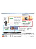
7 If trip Class 20 is selected Smartstart is bypassed. Default: ONSWITCH 3(ON) - Fault reset: Depress the OFF button for 5 seconds to reset a fault trip. Starter will return to OFF mode.(OFF) - Automatic Fault Reset: The starter will make 3 attempts at an auto fault reset separated by 5 minutes intervals. Also allows Manual reset as Fail Modes45 ONOND efault Mode - Always return to last mode with no delay in the event of a power OFFD efault Mode - Always return to last mode with no delay in the event of a power OFFA lways return to last mode with a 10 second delay in the event of a power ONUpon a power failure, return to off SizeInput (lb-in)Output (lb-in)StandardCombination Motor TableWiring SchematicsStandard product wiring diagram shown.
8 As-built product wiring may vary. Product wiring diagram located on starter SwitchNormally Open InputActuatorControl24 VDC, 1A OutputDryInputsRelayOutputsCommonFaultSt atusFireman sOverride12-250 VAC/DC InputAuto RunPermissiveShut DownAuto Run12-250 VAC/DC InputVoltageInputsContactorCoil1 FLA (A)510152025303540 PCB PowerH1 H4 KeypadOverload SettingNormally Open InputNormally Open InputNormally Closed InputMCP(Optional)24 VOutput to contactor coil208-600 VAC60VA output to 24 VAC contactor coil 3 Motor Starter Advanced ControlProtective FeaturesElectronic Overload OperationWhen an alarm occurs, the type of alarm will be indicated by flashing a combination of the hand/off/auto LED s as indicated in the FaultTrips when the starter is activated at a rate exceeding 20 starts per minute.
9 Short 24 VTrips if the starter s combined current drawn from the 24 VDC damper actuator terminals and contactor terminals exceeds 1 RotorTrips when a locked rotor condition is detected for seconds (Smartstart mode only).Max Start TimeTrips if the motor takes more than 10 seconds to start (Smartstart mode only).Out of CalibrationTrips if the FLA setting is determined to be incorrect based on the motor inrush current (safety start mode only).StallTrips if a STALL condition is detected. ( seconds at 300% FLA and current slope not decreasing). Disabled during trip Class 10 or 20. Trip current = 115% of FLA. Trips when the load is greater than the Full Load Ampere setting labeled FLA- (1-40A). The trip time will be determined by the Class 10/20 DIP UnbalanceTrips in the event of a phase failure or phase unbalance greater than 70% (Smartstart mode only)FaultHandOffAutoCycle Fault Alarm Short 24V Alarm 0 Locked Rotor Alarm 0 Max Start Time Alarm 00 Out of Calibration Alarm0 Stall Alarm0 0 Overload Alarm00 Phase Unbalance Alarm000 = off 0 = on* Run and Fault LED s will blink together in the event of a hardware Intended for use with 3-Phase, 50/60Hz Accepts 208-600 VAC, 10% Short Circuit (RMS, Symmetrical) Stand-Alone Overload Unit - 200 KAIC, 600V Max.
10 Standard Starter - 5 KAIC, 600V Max Combination Starter - 100 KAIC, 240V Max. 30 KAIC, 480V Max. 10 KAIC, 600V Max. Ambient Operating Temperature = -20 C to 60 C Ambient Storage Temperature = -40 C to 85 CDANGER Ensure that all connections are properly torqued and enclosure is closed prior to applying power to the device. Ensure all mechanical equipment operated by the starter is clear for safe Operation in case of starter activation. When in AUTO mode, starter may be activated remotely by the control system.!! Operation ModesON (HAND): Press the ON mode button to manually engage (RESET): Pressing the OFF mode button manually disengages the motor. Additionally, the OFF button serves as a Manual Reset.